Supercharger with outlet bars for rotor tip seal support

Inactive Publication Date: 2009-09-17
GM GLOBAL TECH OPERATIONS LLC
View PDF9 Cites 16 Cited by
  • Summary
  • Abstract
  • Description
  • Claims
  • Application Information

AI Technical Summary

Benefits of technology

[0005]The present invention is proposed to improve the serviceability and wear life of tip seals for roots blower and screw type compressor superchargers. Such tip seals may be made of PTFE or other flexible materials having toughness and durability. However operating conditions in the rotor chamber may contribute to flutter and wear which shorten the operating life of the seals. The air outlet opening from the rotor chamber may be generally triangular, having a base adjacent the outlet end of the housing and angled sides leading to a peak spaced from the base of the triangle opposite to the direction of air flow in the housing. In operation, as the seals travel over the outlet opening, the seals move outward in their slots leading to flutter which may shorten their useful lives. As each seal again reaches the center of the outlet opening, it moves from the housing periphery to the recess, or valley, between the associated lobes and is forced back into its groove with the likelihood of increased wear.
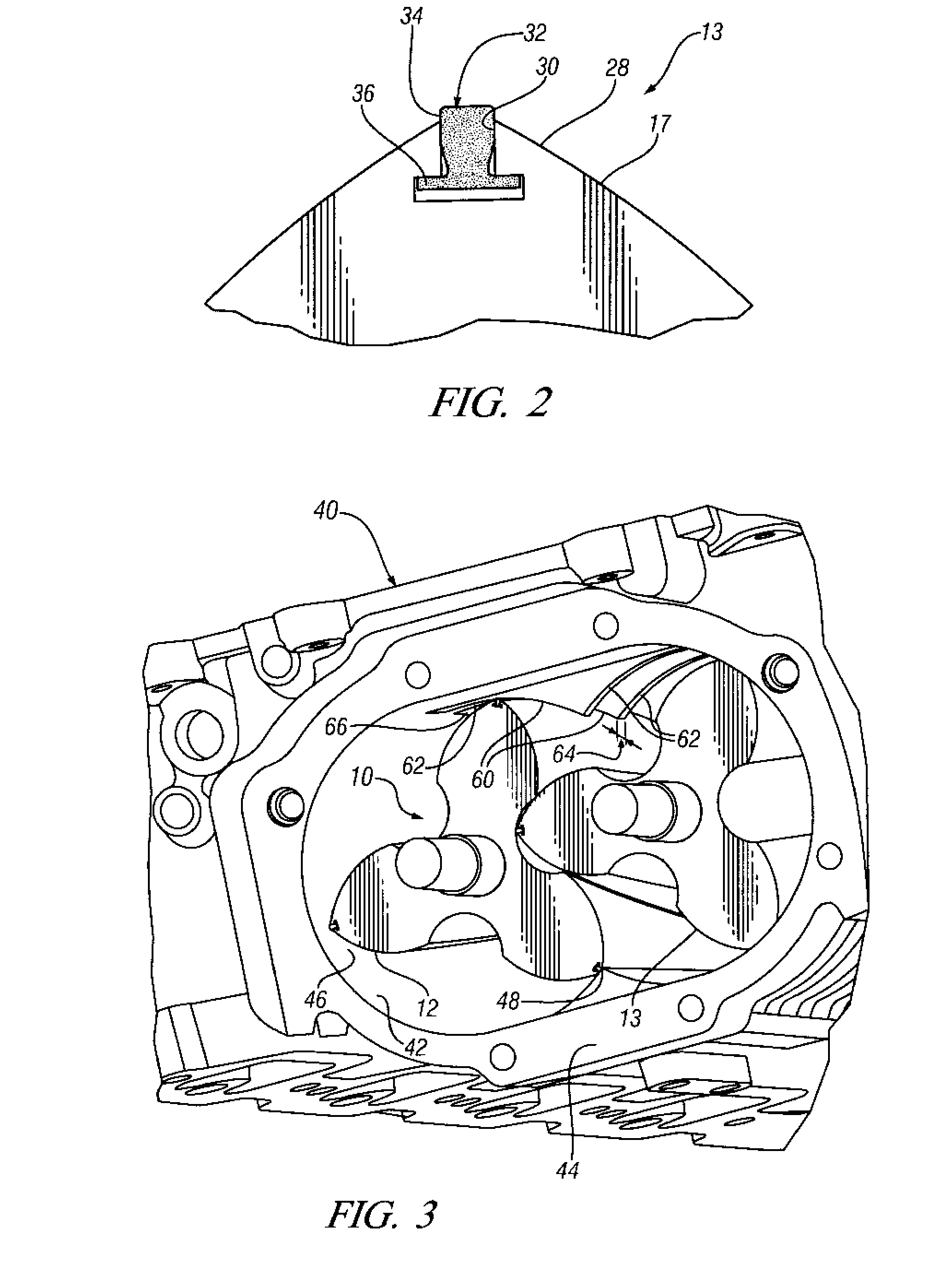
[0006]The invention reduces the flutter and wear of the seals at the outlet opening by providing longitudinally spaced support bars extending laterally across the opening in the directions of rotation of the rotors. The support bars have inner surfaces machined with the associated rotor cavity bores and thus smoothly support the seals as they ride over the support surfaces. The support reduces the flexing of the seals and the resultant wear at the edges of the outlet opening. Each seal contacts a support bar only during inward motion to the center of the opening where the machined bores intersect and the seal is moving into a valley of the associated rotor of the pair. Thus, to reduce edge effect wear of the seals, the width of the support bars is made narrower from the outer edges of the outlet opening to the center, where each seal loses contact with its respective support bar.

Problems solved by technology

However operating conditions in the rotor chamber may contribute to flutter and wear which shorten the operating life of the seals.
In operation, as the seals travel over the outlet opening, the seals move outward in their slots leading to flutter which may shorten their useful lives.
As each seal again reaches the center of the outlet opening, it moves from the housing periphery to the recess, or valley, between the associated lobes and is forced back into its groove with the likelihood of increased wear.
The support reduces the flexing of the seals and the resultant wear at the edges of the outlet opening.

Method used


Image

  • Supercharger with outlet bars for rotor tip seal support
  • Supercharger with outlet bars for rotor tip seal support
  • Supercharger with outlet bars for rotor tip seal support

Examples


Embodiment Construction

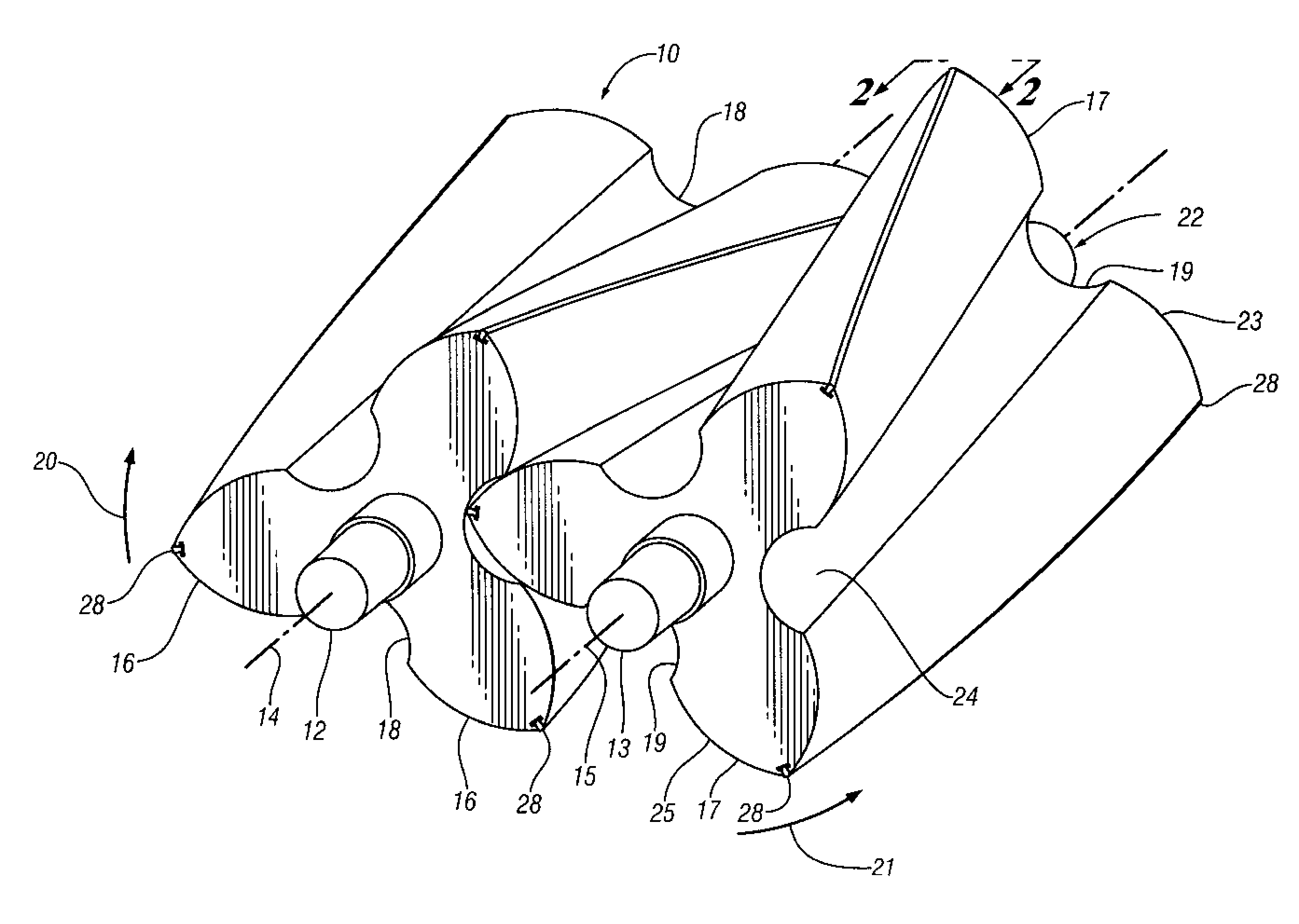
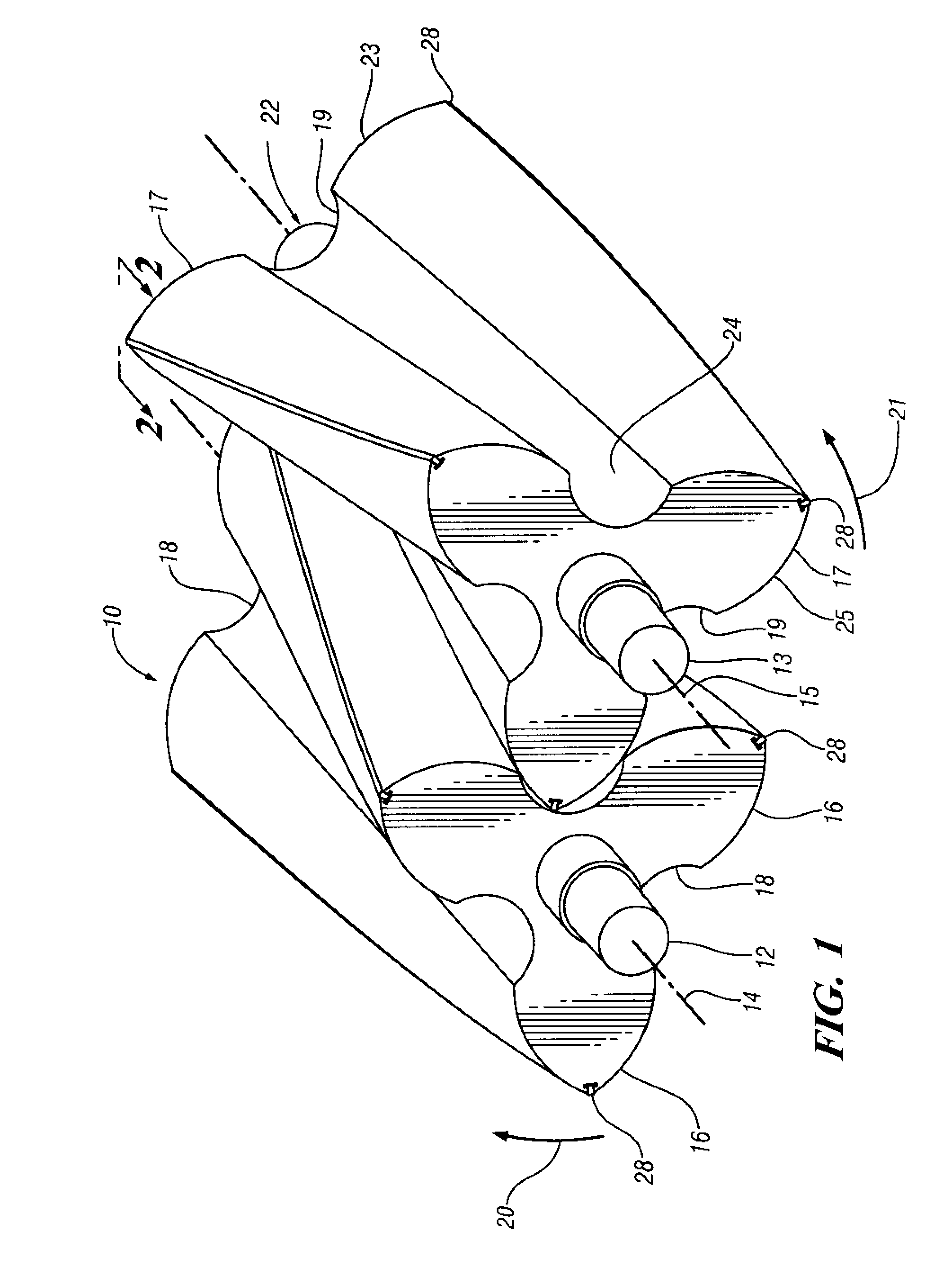
[0012]Referring first to FIGS. 1 and 2 of the drawings in detail, numeral 10 generally indicates a rotor set for a positive displacement supercharger of a known roots type. The set comprises dual rotors 12, 13 rotatable on parallel axes 14, 15. The rotors have helical lobes 16, 17 of opposite hand with alternating valleys 18, 19, respectively, shown interleaved in their use position as in a housing. Rotation in respective clockwise and counterclockwise directions, as shown by arrows 20, 21 in FIG. 1 of the drawings, carries air between the lobes from an inlet 22 at the far end 23 to an outlet 24 adjacent the near end 25 of the rotors as shown in FIG. 1.

[0013]The radial outer ends or tips 28 of the rotor lobes 16, 17, shown also in FIG. 2, are provided with T-slots 30 in which flexible tip seals 32 are retained for sealing radial clearances between the rotors and an outer housing in which the rotor set may be installed. Each seal 32 has a T-shaped cross section with a sealing portion...


PUM


Abstract

The invention is to reduce flutter and wear and improve the serviceability and wear life of tip seals for roots blower and screw type compressor superchargers where used for improved supercharger output and efficiency. As the seals travel over the outlet opening, the seals move outward in their slots, leading to flutter which may shorten their useful lives. As each seal reaches the center of the outlet opening, it is forced back into its groove by engaging a valley of the mating rotor with the likelihood of increased wear. The invention provides longitudinally spaced support bars extending laterally across the opening in the directions of rotation of the rotors. The support bars have inner surfaces machined with the associated rotor cavity bores and thus smoothly support the seals as they ride over the support surfaces. The support reduces the flexing of the seals and the resultant wear. Each seal contacts a support bar only during inward motion to the center of the opening where the machined bores intersect and the seal is moving into a valley of the associated rotor of the pair. To reduce edge effect wear of the seals, the width of the support bars may be made narrower from the outer edges of the outlet opening to the center, where each seal loses contact with its respective support bar.

Description

TECHNICAL FIELD[0001]This invention relates to positive displacement air pumps or superchargers, such as roots type blowers or screw compressors utilized for automotive engine superchargers and other purposes.BACKGROUND OF THE INVENTION[0002]It is known in the art to utilize positive displacement superchargers having lobed rotors for supercharging internal combustion engines and for providing compressed air for other purposes. Such a positive displacement supercharger used as an automotive supercharger may include a housing having a rotor cavity in which a pair of parallel rotors having interleaved lobes rotate to compress air drawn into one end of the housing and discharged through an opening in the cavity wall near an opposite end of the housing. The rotors may be belt driven by the engine through a pulley, or through a gear train, connected directly to the pair of rotors.[0003]Superchargers are very sensitive to running clearances. Tighter clearances between the two rotors and be...

Claims


Application Information

Patent Timeline
IPC IPC(8): F04C27/00F04C18/16F04C18/08
CPCF04C27/001F04C18/16
Inventor PRIOR, GREGORY P.
Owner GM GLOBAL TECH OPERATIONS LLC
Why Eureka
Try Eureka