Rotary internal combustion engine and rotary compressor

a technology of internal combustion engine and compressor, which is applied in the direction of liquid fuel engines, rotary piston liquid engines, machines/engines, etc., can solve the problems of high energy loss of reciprocal piston engines, inability to maintain momentum, constant velocity and direction, and high energy loss of piston engines, so as to reduce pollution, eliminate stress and vibration, the effect of the highest energy-to-fuel ratio

Inactive Publication Date: 2008-08-28
WEBSTER RICHARD COLMAN
View PDF17 Cites 17 Cited by
  • Summary
  • Abstract
  • Description
  • Claims
  • Application Information

AI Technical Summary

Benefits of technology

[0011]It is an object of the. No energy is lost to reciprocal motion or the apparatus required to convert linear motion into rotary motion as would be caused by the use of rods and crankshaft. All motion of these engines either external or internal combustion are purely circular and at a constant velocity. They operate in perfect balance at all times. Since constant, circular motion eliminates stress and vibration, these engines are particularly suited to high temperature operation which, with the low ratio of area to volume at the point of ignition, produces superior, more complete combustion for the highest energy to fuel ratio and hugely reduced pollutants. The use of ceramic compounds, with greater dimensional stability at high temperatures, would facilitate close tolerances, possibly without mechanical seals, that function being replaced by designer lubricants. Circulatory cooling systems would not be needed.

Problems solved by technology

Piston engines pay a high price of energy lost to reciprocal motion.
The inability to maintain momentum, CONSTANT velocity and direction, is expensive.
The mechanical apparatus required to convert that linear motion into usable rotary motion using rods and crankshaft and the energy loss is substantial.
This results in wasted energy and vibration.
In addition the disks are maintained in position with springs that the explosion from the gas can overcome thereby creating an inefficient loss of power that is not present in the pending design.
While this patent provides a motor with rotary motion, the sealing surfaces move in and out thereby creating inefficiency and vibration.

Method used


Image

  • Rotary internal combustion engine and rotary compressor
  • Rotary internal combustion engine and rotary compressor
  • Rotary internal combustion engine and rotary compressor

Examples


Embodiment Construction

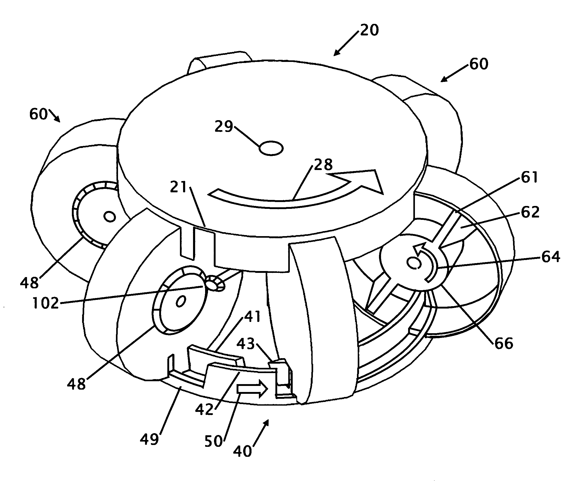
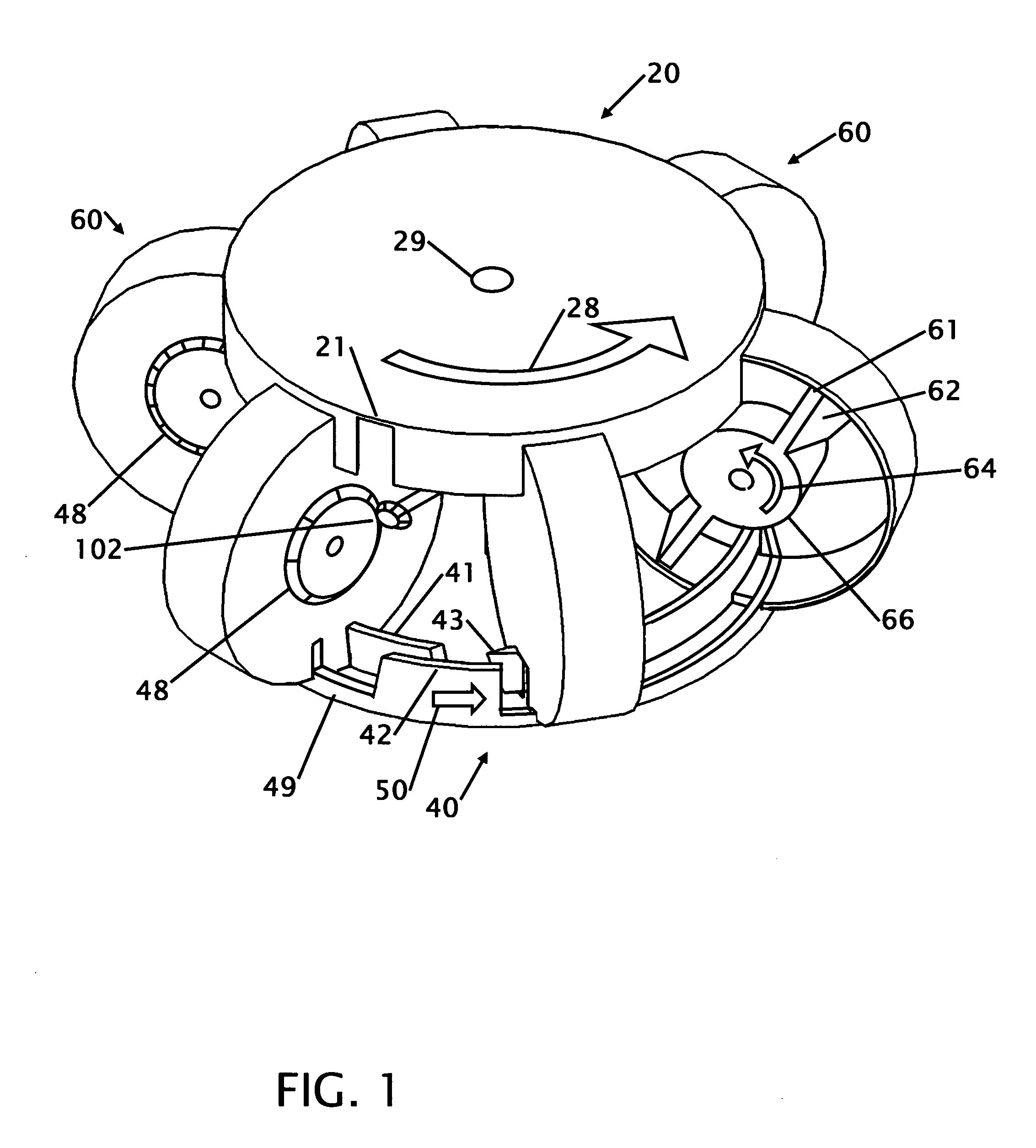
[0030]FIG. 1 shows an isometric cut away view of a six disk rotary internal combustion engine. The six rotors 60 are equally spaced around the center 29 at 60 degree intervals. A valve upper ring 20 is located on the top and above the six rotors 60. A lower valve ring 40 is located on the bottom or under the six rotors 60. The lower valve ring 40 has two raised rims where the inner rim is the head ring 41 and the outer rim is the compression ring 42 that are concentric. Each upper valve ring has two ring slots 21 located on opposite sides of the upper ring. The rim of the upper valve ring 20 and the ring slots 21 pass through each of the six rotors 60 to provide an opening for air intake and air exhaust. A more detailed description of the intake and exhaust is shown and described in FIG. 4-6. The rim of the lower valve ring 40 and the ring slots 49 and 43 pass through each of the six rotors 60 to provide an opening for the piston 61 located on the rotor to enter for compression and ...


PUM


Abstract

The rotary internal combustion engine is a rotary internal combustion engine that uses the unique combination of multiple rotors on a vertical axis with piston vanes, which are intersected by horizontally oriented valve rings so that rotating rotors intersect gaps on the rotating valve rings, thus creating the intake compression and power and exhaust cycles on this internal combustion engine. The unique design allows the motor to operation as either a motor or pump. High volume of compressed air virtually eliminates the need for a storage tank. These engines are an elegant solution that fulfills the century long quest for quiet, clean, highly efficient rotary power. When available, the demand for the benefits of rotary piston power in air, surface, and marine applications, will be immediate and rewarding.

Description

CROSS REFERENCE TO RELATED APPLICATION[0001]This application claims the benefit of Provisional 60 / 903,929 filed Feb. 28, 2007 the entire contents of which is hereby expressly incorporated by reference herein.DESCRIPTION[0002]1. Field of the Invention[0003]This invention relates to improvements in a rotary engine or pump. More particularly, the present rotary engine or pump uses a pair of opposed rotors with vanes that pass though the rotors. The two vanes are on opposite sides of the rotor core and the rotor case which closely contains the core and vanes which rotate over the top and to the center. The disk rotates horizontally at the same RPM as the rotor to compress gas for combustion. The combustion continues to push the vanes to generate power. When the engine is driven air is compressed with the vanes to turn the engine into a air compressor.[0004]2. Background of the Invention[0005]Piston engines pay a high price of energy lost to reciprocal motion. A piston accelerates, de-ac...

Claims


Application Information

Patent Timeline
Patent Type & Authority Applications(United States)
IPC IPC(8): F02B53/00F04C3/04
CPCF01C3/02Y02T10/17F02B53/00Y02T10/12
Inventor WEBSTER, RICHARD COLMAN
Owner WEBSTER RICHARD COLMAN
Why Eureka
Try Eureka