Method of starting operation of fuel cell system

a fuel cell and system technology, applied in the direction of fuel cells, electrochemical generators, electrical equipment, etc., can solve the problems of energy loss in the dc/dc converter b>2, and the inability to start the fuel cell b>4

Active Publication Date: 2009-09-17
HONDA MOTOR CO LTD
View PDF2 Cites 8 Cited by
  • Summary
  • Abstract
  • Description
  • Claims
  • Application Information

AI Technical Summary

Benefits of technology

[0010]The present invention has been made to solve the above problems, and an object of the present invention is to provide a method of starting operation of a fuel cell system in which, at the time of starting operation of the fuel cell system, electrical energy is directly supplied to an air pump bypassing a DC / DC converter, and operation of a fuel cell system is started easily and reliably.
[0013]In the present invention, at the time of starting operation of the fuel cell system, the energy storage is directly connected to the power feeding circuit through the bypass circuit, bypassing the DC / DC converter. Therefore, in the state where the DC / DC converter is stopped, electrical energy can be supplied directly from the energy storage to the air pump. Thus, switching losses in the DC / DC converter can be avoided, and improvement in the efficiency is achieved. Accordingly, electrical energy is efficiently supplied from the energy storage to the air pump, and size reduction of the energy storage is achieved easily.

Problems solved by technology

Therefore, energy losses occur in the DC / DC converter 2.
Further, if any failure occurs in the DC / DC converter 2, it is not possible to start operation of the fuel cell 4.

Method used


Image

  • Method of starting operation of fuel cell system
  • Method of starting operation of fuel cell system
  • Method of starting operation of fuel cell system

Examples


first embodiment

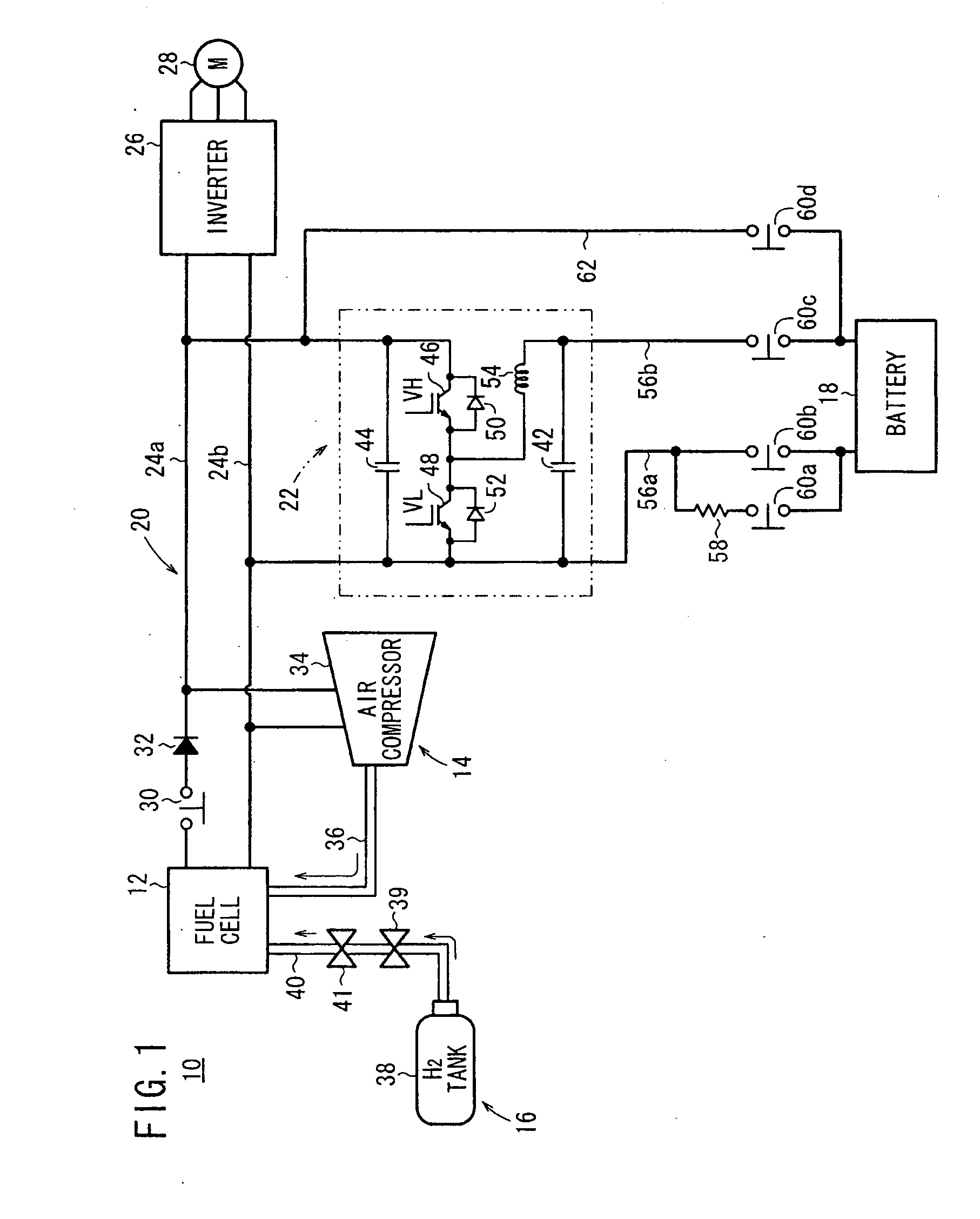
[0022]FIG. 1 is a diagram schematically showing a structure of a fuel cell system 10 mounted in a vehicle to which a method of starting operation according to the present invention is applied.

[0023]The fuel cell system 10 includes a fuel cell 12, an oxygen-containing gas supply apparatus 14 for supplying an oxygen-containing gas to the fuel cell 12, a fuel gas supply apparatus 16 for supplying a fuel gas to the fuel cell 12, a coolant supply apparatus (not shown) for supplying a coolant to the fuel cell 12, an energy storage (hereinafter referred to as a battery) 18, and an DC / DC converter 22 capable of connecting the fuel cell 12 and the battery 18 on a power feeding circuit 20.

[0024]The fuel cell 12 and the DC / DC converter 22 are connectable to an inverter 26 through bus lines 24a, 24b of the power feeding circuit 20. Electrical current (electrical energy) is supplied to a drive motor (electric motor) 28 for running of the vehicle through the inverter 26.

[0025]Though not shown, th...

second embodiment

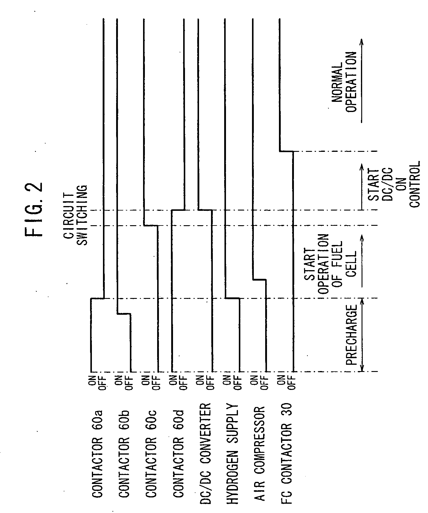
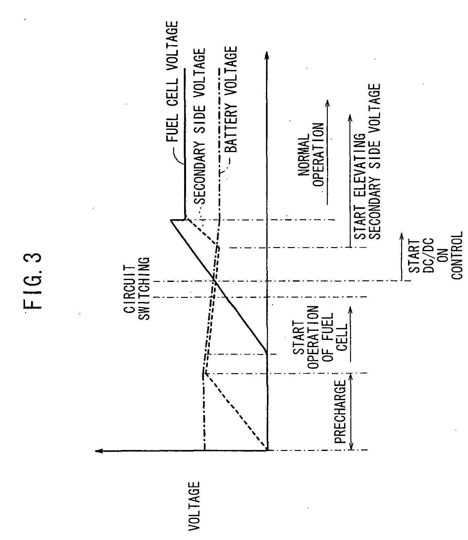
[0045]In the second embodiment, firstly, the contactors 60a, 60b are turned on to start precharging of the secondary capacitor 44 of the DC / DC converter 22. Then, after the contactor 60b is turned on, the contactor 60a is turned off to finish precharging. When the contactor 60a is turned off, the contactor 30 at the outlet of the fuel cell 12 is turned on to connect the fuel cell 12 to the power feeding circuit 20.

[0046]Further, the fuel gas supply apparatus 16 and the oxygen-containing gas supply apparatus 14 are operated to start operation of the fuel cell 12. Then, after the contactor 60c is turned on, the contactor 60d is turned off to perform operation of the fuel cell system 10 by electrical energy supplied from the fuel cell 12.

[0047]As described above, in the second embodiment, even if any failure occurs in the DC / DC converter 22, the battery 18 is connected to the air compressor 34 bypassing the DC / DC converter 22, and the electrical energy is supplied to the air compressor...


PUM

PropertyMeasurementUnit
voltageaaaaaaaaaa
voltageaaaaaaaaaa
electrical energyaaaaaaaaaa

Abstract

A fuel cell system includes a fuel cell, a battery, and a DC / DC converter capable of connecting the fuel cell and the battery on a power feeding circuit. A method of starting operation of the fuel cell system includes the steps of connecting a bypass line connected to a battery for bypassing the DC / DC converter to the power feeding circuit, and directly supplying electrical energy from the battery to an air compressor of an oxygen-containing gas supply apparatus through the bypass line in a state where the fuel cell is disconnected from the power feeding circuit.

Description

BACKGROUND OF THE INVENTION[0001]1. Field of the Invention[0002]The present invention relates to a method of starting operation of a fuel cell system including a fuel cell for generating electricity using a fuel gas supplied from a fuel gas supply apparatus and an oxygen-containing gas supplied from an oxygen-containing gas supply apparatus, and a DC / DC converter capable of connecting the fuel cell and an energy storage on a power feeding circuit.[0003]2. Description of the Related Art[0004]The fuel cell is a system for obtaining direct current electrical energy by electrochemical reactions of a fuel gas (chiefly hydrogen-containing gas) supplied to an anode and an oxygen-containing gas supplied to a cathode.[0005]The fuel cell is promising for an application to a fuel cell vehicle, i.e., for use in a vehicle such as an automobile. For example, in a known fuel cell system (fuel cell automobile), the fuel cell and a motor driven by an inverter are directly connected, and a DC / DC conv...

Claims


Application Information

Patent Timeline
Patent Type & Authority Applications(United States)
IPC IPC(8): H01M8/00
CPCH01M8/04089H01M8/04223H01M8/04559H01M8/04567Y02E60/50H01M8/04947H01M8/04955H01M16/006H01M2008/1095H01M8/04888Y02E60/10H01M8/04225H01M8/04302
Inventor OJIMA, KUNIAKIAOYAGI, SATOSHI
Owner HONDA MOTOR CO LTD
Why Eureka
Try Eureka