Decanter type centrifugal separator
a centrifugal separator and separator technology, applied in the direction of centrifuges, rotary centrifuges, etc., can solve the problems of difficult to absorb the torsional vibration generated by the conveyor at each transmission part, damage to an internal gear, and accumulation of plays in the differential gear unit or in the connection parts, etc., to achieve high viscosity, increase the degree of damping of self-excited vibration, and high viscosity
- Summary
- Abstract
- Description
- Claims
- Application Information
AI Technical Summary
Benefits of technology
Problems solved by technology
Method used
Image
Examples
first embodiment
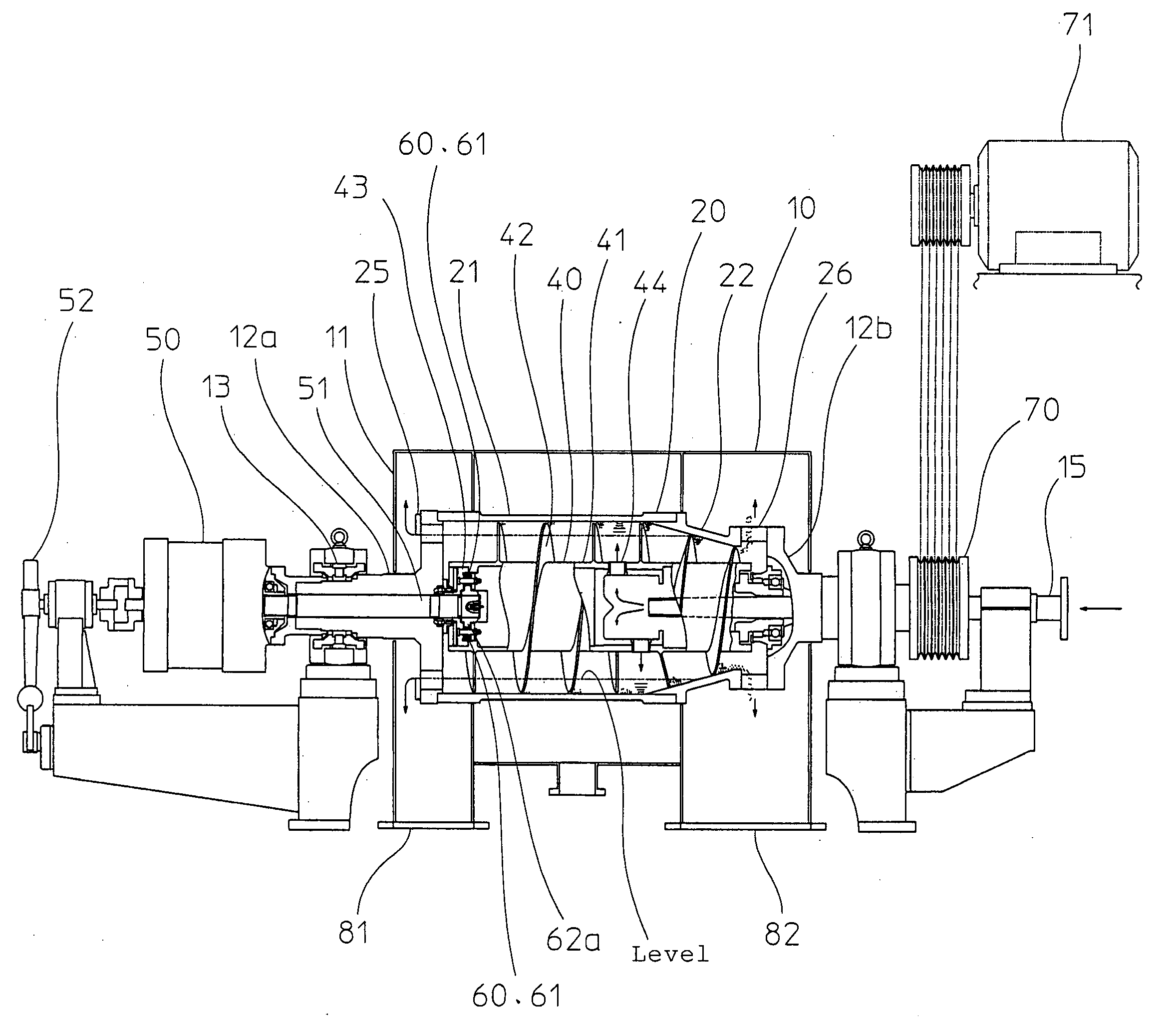
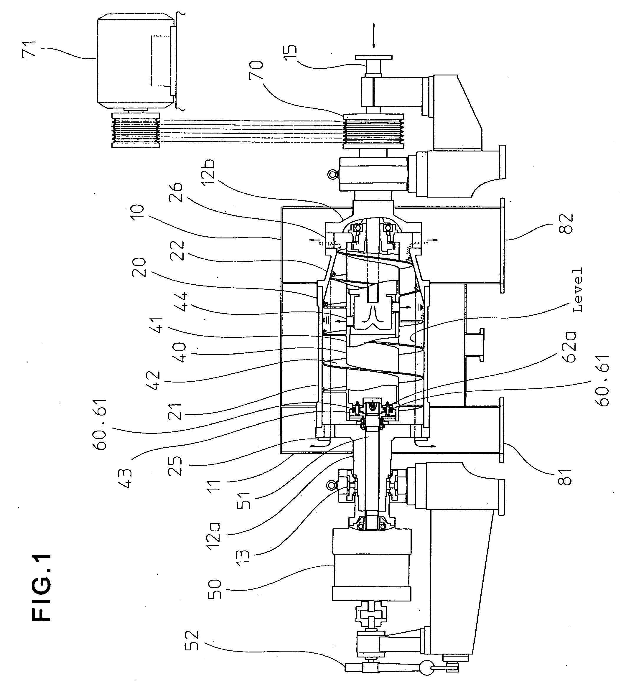
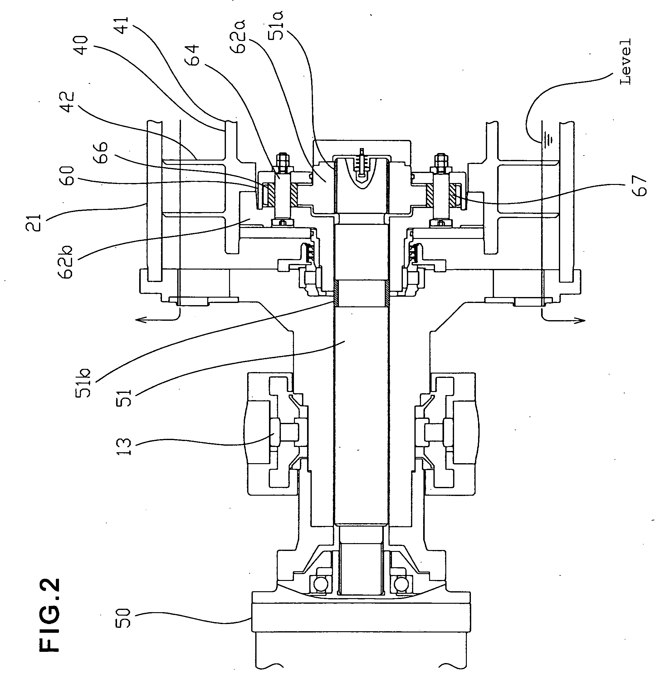
[0026]FIG. 1 and FIG. 2 show the present invention.
[0027]A decanter type centrifugal separator 10 comprises a bowl 20 having a cylindrical part 21, a conical part 22, a separated liquid discharge dam part 25, and a dewatered solid discharge port 26; a screw conveyor 40 for axially conveying sedimentation solid that is inserted into the bowl 20, and is arranged so that it is coaxial with the bowl 20, and can be rotated at a speed different from that of the bowl 20, as well as processed liquid feed means 15; a separated liquid discharge port 81; a solid discharge port 82; drive means 71; and a differential gear unit 50 which produces a difference in speed between the bowl 20 and the screw conveyor 40.
[0028]The bowl 20 of the decanter type centrifugal separator 10 has an inside diameter of 740 mm, and the bowl 20 is rotated at a speed of 1700 to 2800 min−1 for a centrifugal force of 1200 G to 3200 G, while an internal screw conveyor flight 42 is rotated at a speed of 1620 to 2760 min−1...
third embodiment
[0043]FIG. 8 and FIG. 9 show the present invention.
[0044]The same components as those in the first embodiment will be provided with the same reference numerals.
[0045]In the decanter type centrifugal separator 10 pertaining to the present embodiment, the entire assembly inside the torque transmission mechanism 60, 61 as given in the first embodiment or second embodiment that is included in the joint part 43 on the side of the screw conveyor 40 of the drive transmission shaft 51 between the differential gear unit 50 and the screw conveyor 40 is immersed in a high viscosity liquid, such as silicone oil, or the like, or a high viscosity substance, such as silicone rubber (initially liquid, but vulcanized into a gummy state as time elapses), or the like, as a measure against torsional self-excited vibration of the screw conveyor 40 that can occur between the bowl 20 and the tip of the screw conveyor flight 42 through the treatment substances, such as PVC crystalline particles, or the lik...
PUM
 Abstract
Description
Claims
Application Information
 - R&D
- Intellectual Property
- Life Sciences
- Materials
- Tech Scout
- Unparalleled Data Quality
- Higher Quality Content
- 60% Fewer Hallucinations
Browse by: Latest US Patents, China's latest patents, Technical Efficacy Thesaurus, Application Domain, Technology Topic, Popular Technical Reports.
© 2025 PatSnap. All rights reserved.Legal|Privacy policy|Modern Slavery Act Transparency Statement|Sitemap|About US| Contact US: help@patsnap.com


