Time lag measuring device, distance measuring apparatus and distance measuring method

a technology of time lag and measuring device, which is applied in the direction of recording signal processing, instruments, and using reradiation, etc., can solve the problems of limiting the increase of the generated frequency of the clock signal, the disadvantage of the proposed technique in terms of further speeding up the measurement, and the inability to accurately obtain the measurement. , to achieve the effect of accurate measuremen

Inactive Publication Date: 2009-09-17
KK TOPCON
View PDF8 Cites 5 Cited by
  • Summary
  • Abstract
  • Description
  • Claims
  • Application Information

AI Technical Summary

Benefits of technology

[0163]According to the time lag measuring device of the present invention, an error included in the detected phase difference is corrected, the error attributed to one of an error in the reference signal, an error in the phase difference for the delay timing, and an error between the two reference signals, and the generation time lag Δt is obtained on the basis of the phase difference thus corrected. Accordingly, even in a case where the reference signals have an error in the amplitudes and the phase difference, the time lag between the generation timings for the measurement pulse signals can be accurately measured.
[0164]In addition, in the distance measuring apparatus and the distance measuring method according to the present invention, the time lag between the pulse signals can be accurately obtained by use of the time lag measuring device according to the present invention. Consequently, the distance calculated according to the time lag can be made accurate.

Problems solved by technology

However, even though the frequency in the clock signal has to be increased to improve the measurement accuracy in such measuring, there is a limitation on the increase of the generated frequency in the clock signal.
This leads to an increase of the measurement time, and hence to a problem in a practical use.
The foregoing proposed technique, however, requires the start signal and the stop signal to be generated two or more times, and then to be detected two or more times. For this reason, the proposed technique has a disadvantage in terms of further speeding-up of the measurement.

Method used


Image

  • Time lag measuring device, distance measuring apparatus and distance measuring method
  • Time lag measuring device, distance measuring apparatus and distance measuring method
  • Time lag measuring device, distance measuring apparatus and distance measuring method

Examples


embodiment 1

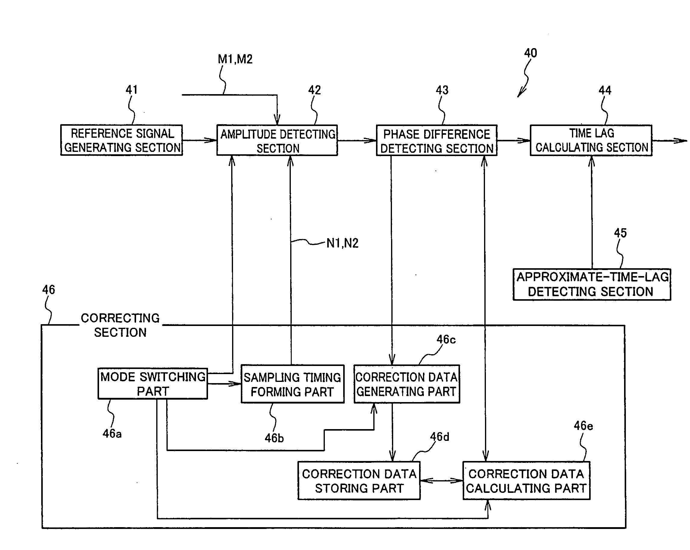
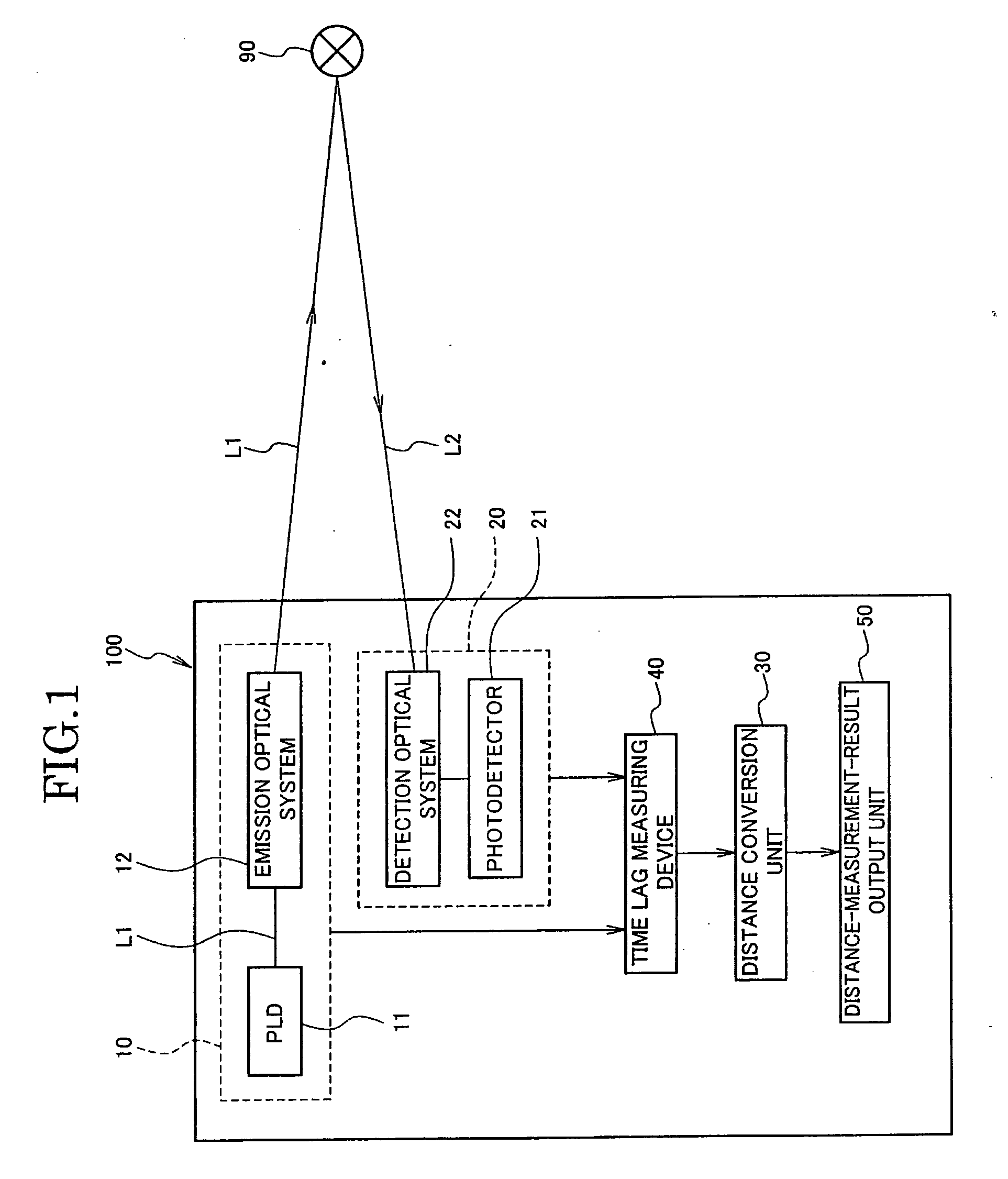
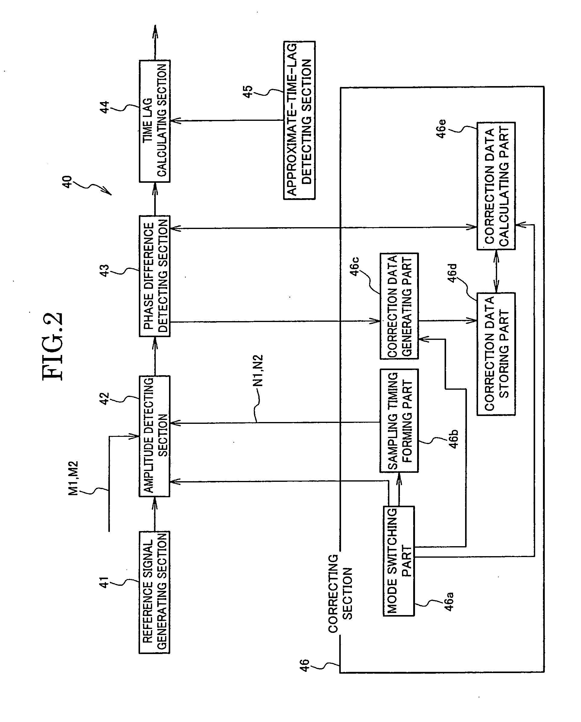
[0223]The illustrated survey instrument 100 has a configuration including: a measuring beam emission unit 10 (measurement-pulse-wave emission unit) that emits a pulsed laser beam L1 (measuring pulse wave) to an object of distance measurement (hereinafter, called a distance-measuring object) 90; a reflected laser beam detection unit 20 (reflected-pulse-wave detection unit) that detects a reflected laser beam L2 (reflected pulse wave) obtained by reflecting the laser beam L1 by the distance-measuring object 90; a time lag measuring device 40 that outputs a pulsed start signal M1 (first pulse signal) at an emission timing of the laser beam L1 from the measuring beam emission unit 10, outputs a pulsed stop signal M2 (second pulse signal) at a detection timing of the reflected laser beam L2 by the reflected laser beam detection unit 20, and then measures a time lag Δt between the output timing of the start signal M1 and the output timing of the stop signal M2; a distance conversion unit ...

modified example 1

[0333]Each mode of the aforementioned embodiment has a configuration in which the reference signal generating section 41 separately generates and also separately outputs the first reference signal S1 of the sinusoidal signal and the second reference signal S2 of the cosine wave signal, for example, as shown in FIG. 5. However, as shown in FIG. 26, for example, another configuration may be applied in which the reference signal generating section 41 does not include the cosine wave generating part (Cos) 41c but includes a delay circuit 42d for processing the sinusoidal reference signal S1 generated by a sine wave generating part (Sin) 41b, to delay the reference signal S1 by a time corresponding to a phase difference of π / 2 [rad] ((π / 2) [rad]_(2n−1); n=1, 2, . . . ) in the reference signal S1.

[0334]In other words, the reference signal generating section 41 primitively generates only one reference signal (sinusoidal signal) S1, and the delay circuit 42d generates a new reference signal...

embodiment 2

[0339]Each of the modes described as Embodiment 1 is for a case where there are two reference signals, and shows that the phase difference between the two reference signals is approximately π / 2 [rad], and that the two reference signals are sampled at the same time (at the same timing). A time lag measuring device and a distance measuring apparatus according to the present invention are not limited to this embodiment, and can employ a configuration that can be substantially considered as the same as this embodiment.

[0340]Specifically, a set of sampling values (amplitude values) may be obtained by sampling a single reference signal at two timings with a time lag corresponding to the phase difference, instead of obtaining a set of sampling values by sampling two reference signals having a phase difference at the same time.

[0341]For example, FIG. 28 shows a mode corresponding to the embodiment shown in FIG. 26. In the illustrated embodiment, a mode switching part 46g accepts input from ...


PUM


Abstract

In measuring a certain time lag between generations of two pulse signals, a time lag measuring device prevents errors in measurement results even with an error in two reference signals for measuring the time lag. The device measures a time lag between a start signal M1 and a stop signal M2 and includes a reference signal generating section 41 generating two reference signals S1, S2 having a phase difference π/2, and an amplitude detecting section 42 detects amplitudes A11, A12 and A21, A22 of the reference signals S1, S2 at generation timings for the start signal M1 and the stop signal M2, a phase difference detecting section 43 calculating a phase _ of the reference signals S according to each set of the amplitudes (A11, A12) and (A21, A22), and a correcting section 46 correcting the calculated phase using correction data for error correction in the reference signals S1, S2.

Description

TECHNICAL FIELD[0001]The present invention relates to a time lag measuring device, a distance measuring apparatus and a distance measuring method, and, in particular, relates to improvement in measurement of a time lag between pulse signals at a very short time interval.BACKGROUND ART[0002]A distance measuring apparatus such as a current survey instrument irradiates an object of distance measurement with a measuring wave such as a laser beam or a microwave, detects a reflected wave (hereinafter, collectively called a measuring wave) reflected from the object of distance measurement, finds the distance of the reciprocating movement of the measuring wave according to the time lag between the emission and the detection of the measuring wave, and thereby calculates the distance (one-way distance) to the object.[0003]Here, the measuring of the time lag (time interval) is performed, for example: by generating a high frequency clock signal having a known extremely-short cycle as compared w...

Claims


Application Information

Patent Timeline
Patent Type & Authority Applications(United States)
IPC IPC(8): G06F11/07G01S17/10G01S7/4865
CPCG01S7/487G01S7/4865G04F10/06G01S17/10
Inventor OHISHI, MASAHIROTOKUDA, YOSHIKATSUOHTOMO, FUMIO
Owner KK TOPCON
Why Eureka
Try Eureka