

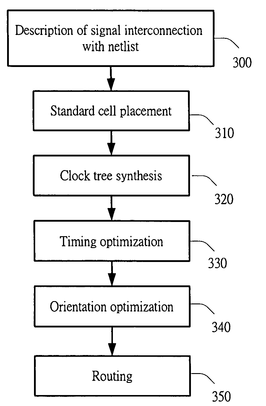
Orientation optimization method of 2-pin logic cell
a logic cell and orientation optimization technology, applied in the field of determining the orientation of a 2pin logic cell, can solve the problems of difficult to properly adjust the orientation of the cells, the connection between cells is quite complicated, and the current computer-aided design tool does not involve optimizing the orientation of a 2-bin logic cell to further reduce propagation delay and routing length
- Summary
- Abstract
- Description
- Claims
- Application Information
AI Technical Summary
Benefits of technology
Problems solved by technology
Method used
Image

Examples
Embodiment Construction
[0050]The present invention will now be described more specifically with reference to the following embodiments. It is to be noted that the following descriptions of preferred embodiments of this invention are presented herein for purpose of illustration and description only; it is not intended to be exhaustive or to be limited to the precise form disclosed.
[0051]According to an orientation optimization method of the present invention, a “paths-based flip” algorithm is adopted. For all 2-pin logic cells including inverters, buffers and delay cells, the “paths-based flip” orientation optimization method applies.
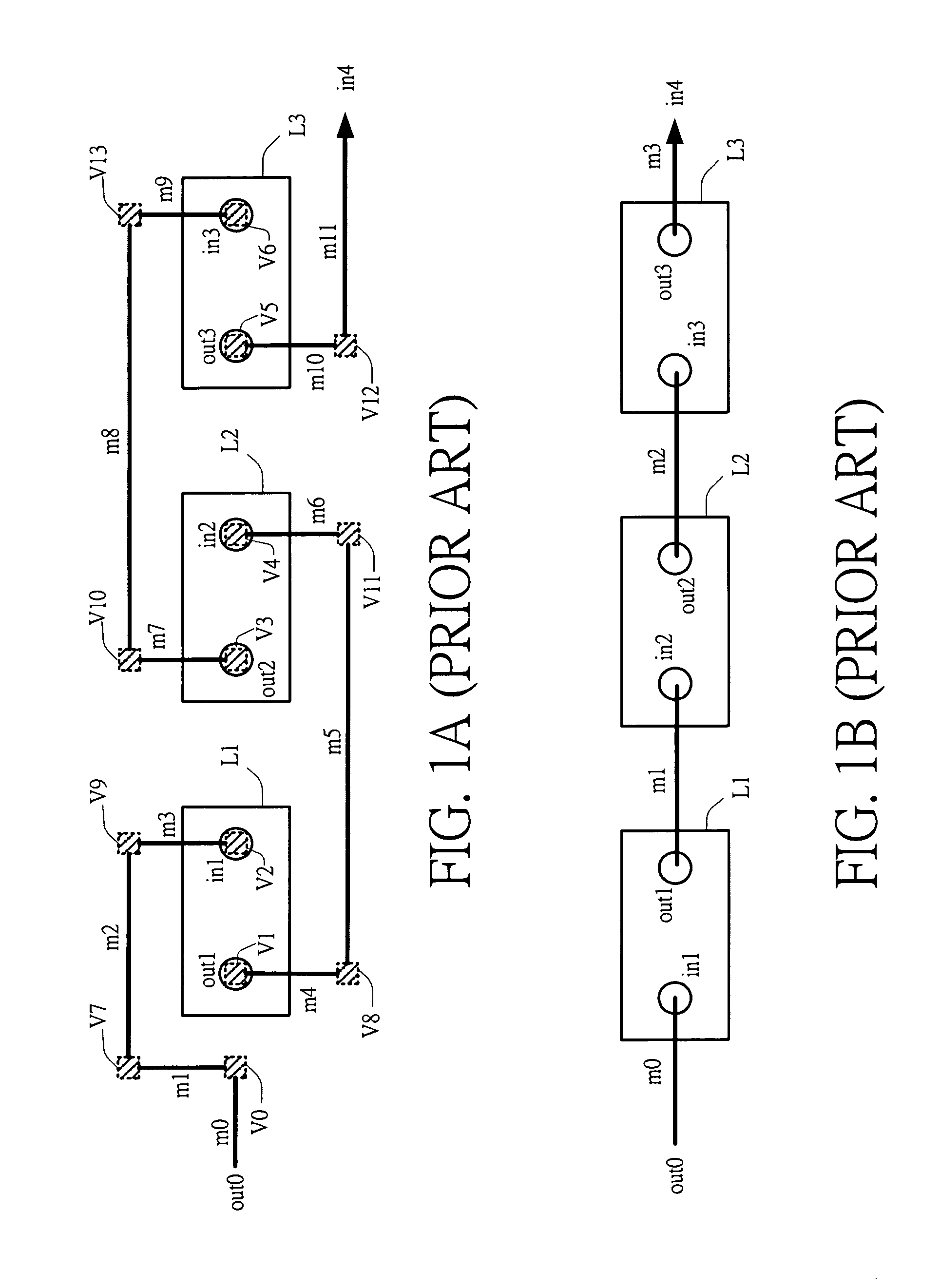
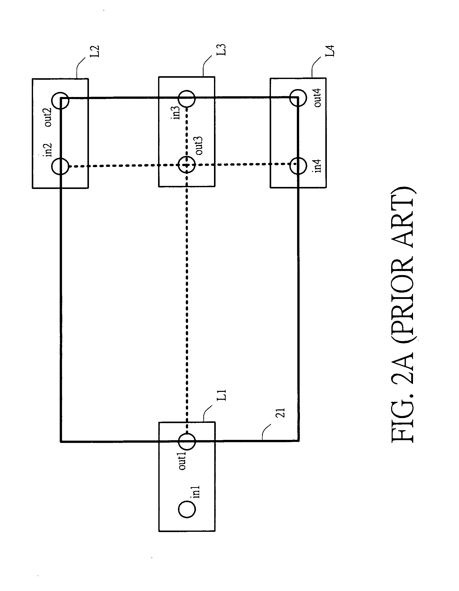
[0052]Please refer to FIG. 4. A simple circuitry is exemplified to describe the “paths-based flip” orientation optimization method according to an embodiment of the present invention. The routing starts from a signal source s0 and extends through three 2-pin logic cells L1, L2 and L3 in sequence, thereby constituting a signal chain path I. For attracting inputs (in1, in2, in3)...
PUM
 Abstract
Description
Claims
Application Information