Fuel Supply System For An Internal Combustion Engine

a fuel supply system and internal combustion engine technology, applied in the direction of liquid fuel feeders, fuel injecting pumps, machines/engines, etc., can solve the problems of fuel not being able to be delivered to the intake passage the volume of pipe that needs to be charged with fuel is significantly larger, and the fuel is not able to be delivered to the fuel injector by the feed pump, so as to improve the startability of the internal combustion engin

Inactive Publication Date: 2009-09-24
TOYOTA JIDOSHA KK
View PDF20 Cites 15 Cited by
  • Summary
  • Abstract
  • Description
  • Claims
  • Application Information

AI Technical Summary

Benefits of technology

[0012]This invention thus provides a fuel supply system for an internal combustion engine, which is capable of improving startability of an internal combustion engine that includes a fuel injection mechanism for injecting fuel at high pressure into a cylinder (i.e., in-cylinder fuel injector) and a fuel injecting mechanism for injecting fuel into an intake passage or an intake port (i.e., an intake passage fuel injector).
[0014]According to this first aspect, the high pressure pump which is driven by the internal combustion engine does not operate during startup of the internal combustion engine. In this case, the internal combustion engine is started by injecting fuel that has been pressurized by the low pressure pump from the low pressure fuel injection mechanism via the low pressure fuel supply passage. In this case, during startup of the internal combustion engine when the pressure of fuel in the low pressure fuel supply passage is low, the pulsation reducing mechanism closes off communication between the low pressure fuel supply passage and the high pressure fuel supply passage. Therefore, fuel can be delivered to the low pressure fuel injection mechanism simply by charging the low pressure fuel supply passage with fuel using the low pressure pump. Accordingly, there is no need to charge the high pressure fuel supply passage with fuel using the low pressure pump so the low pressure fuel supply passage and the branch passage that provides communication between the low pressure fuel supply passage and the high pressure pump can be charged with fuel quickly, and fuel can be quickly injected from the low pressure fuel injection mechanism. As a result, startability of an internal combustion engine provided with a fuel injection mechanism that injects fuel at high pressure into the cylinder and a fuel injection mechanism that injects fuel into the intake passage or intake port can be improved.
[0018]According to this kind of pipe structure, in a V-type internal combustion engine, for example, a plurality of cylinders are arranged in each bank. Accordingly, a high pressure fuel injection mechanism and a low pressure fuel injection mechanism are provided for each cylinder and there is a tendency for the length of the high pressure fuel supply passage that supplies fuel to the high pressure fuel injection mechanism to be long. Therefore, in this kind of engine, unless communication is closed off between the high pressure fuel supply passage and the low pressure fuel supply passage during startup of the internal combustion engine, it will take more time to charge the pipe volume with fuel using the low pressure pump than it would with an internal combustion engine of another configuration because the pipe volume is increased due to the longer high pressure pipe supply passage. The pulsation damper according to the foregoing aspect enables communication between the high pressure fuel supply passage and the low pressure fuel supply passage to be closed off by the spring force of the spring of the pulsation damper against the pressure of fuel when the pressure of the fuel in the low pressure fuel passage is low during startup of the internal combustion engine. As a result, an even greater operational effect can be displayed in this kind of V-type internal combustion engine, for example.
[0020]According to this structure, the spring constant of the pulsation damper is set to keep the high pressure fuel supply passage closed off from the low pressure fuel supply passage, even if the fuel pressure is one that enables the internal combustion engine to start well by fuel being injected from the low pressure fuel injection mechanism. Therefore, fuel can be injected well from the low pressure fuel injection mechanism while the high pressure fuel supply passage is kept closed off from the low pressure fuel supply passage so the internal combustion engine can be started quickly.
[0022]According to this structure, the pulsation damper can close off communication between the high pressure fuel supply passage and the low pressure fuel supply passage.

Problems solved by technology

At engine startup in this kind of a direct injection engine having only an in-cylinder fuel injector, fuel is unable to be delivered by the high pressure fuel pump until the engine turns over.
However, in this kind of engine, the following problems occur when starting the engine by injecting fuel with an intake passage fuel injector.
When fuel is delivered by a feed pump at engine startup, the volume of pipe that needs to be charged with fuel becomes significantly larger.
Therefore, fuel is unable to be delivered to the intake passage fuel injector by the feed pump unless both the low pressure pipe and the high pressure pipe are charged with fuel.
As a result, it takes time for the feed pressure to rise, thereby adversely affecting startability (i.e., increasing the start time).

Method used


Image

  • Fuel Supply System For An Internal Combustion Engine
  • Fuel Supply System For An Internal Combustion Engine
  • Fuel Supply System For An Internal Combustion Engine

Examples


Embodiment Construction

[0032]Hereinafter, example embodiments of the invention will be described in detail with reference to the accompanying drawings. In the following description, like parts with be denoted by like reference numerals. Like parts will also be referred to by the same nomenclature and will have the same function. Therefore, detailed descriptions of those parts will not be repeated.

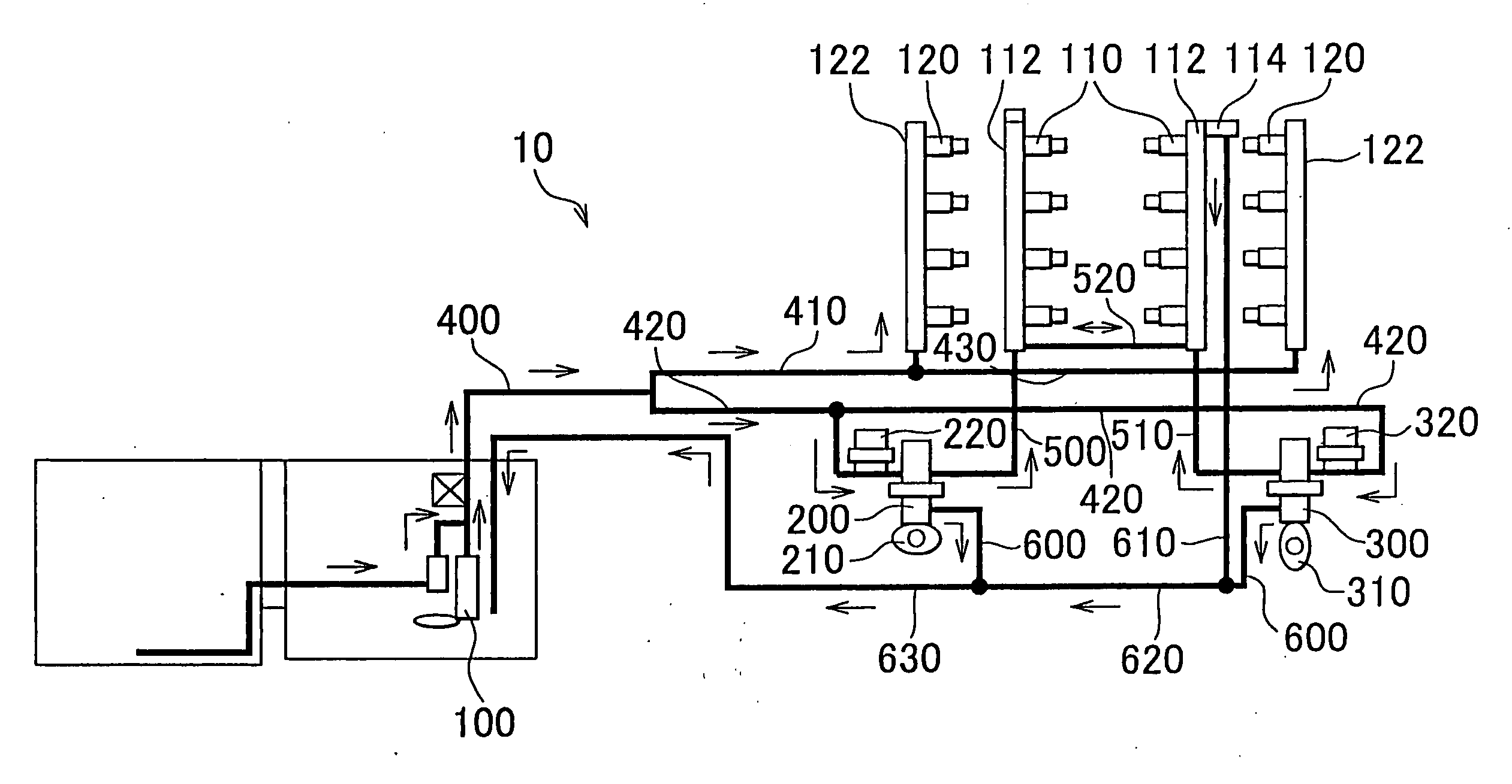
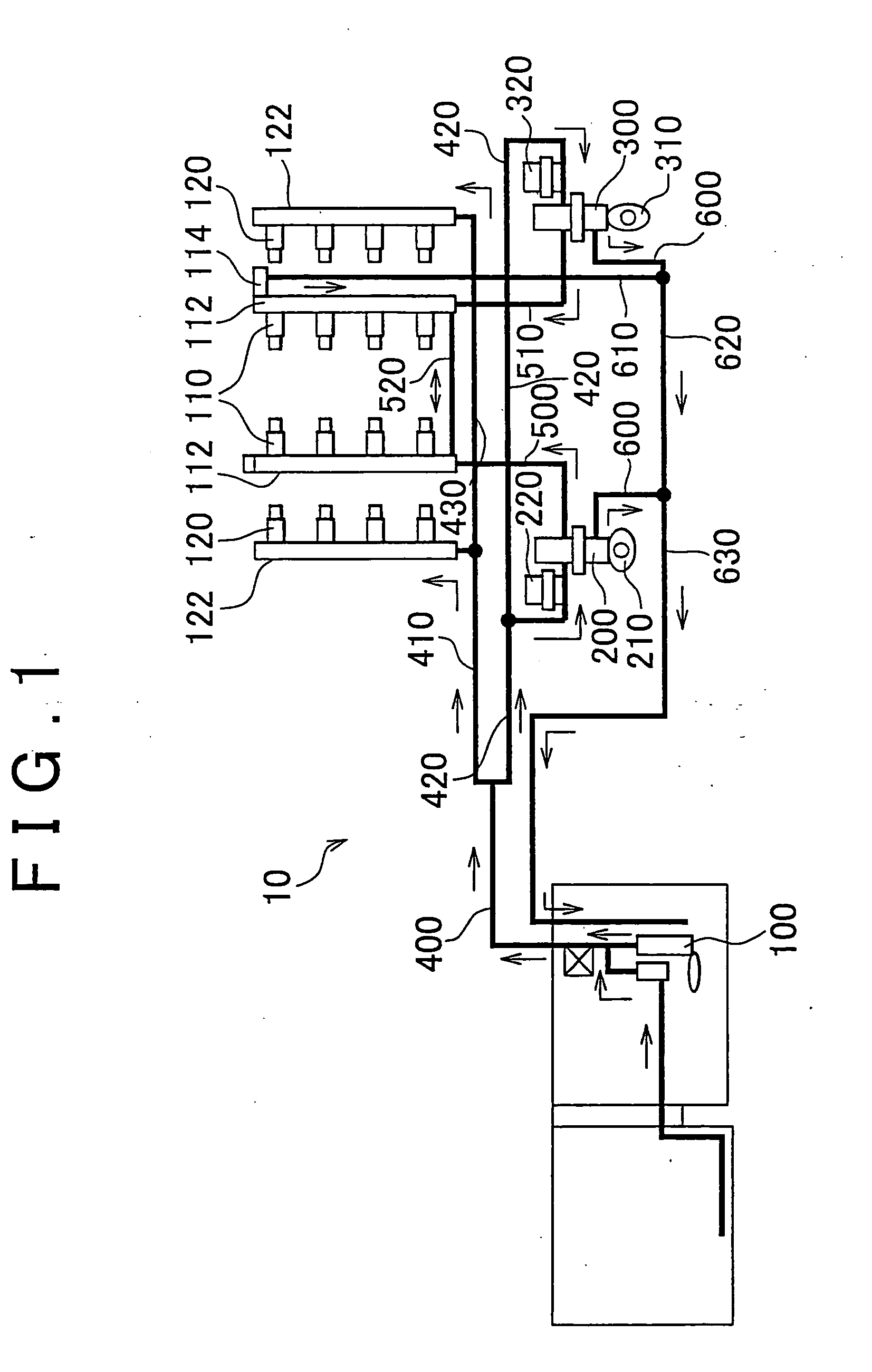
[0033]FIG. 1 shows a fuel supply system 10 which serves as a fuel supply system according to one example embodiment of the invention. The engine is a V-type 8 cylinder gasoline engine which has, in each cylinder, an in-cylinder fuel injector 110 for injecting fuel in each cylinder and an intake passage fuel injector 120 for injecting fuel into the intake passage of each cylinder. Incidentally, the invention is not limited to being applied to this kind of engine. That is, the invention may also be applied to a gasoline engine having another configuration or to a common rail type diesel engine. Further, the number ...


PUM


Abstract

A pulsation damper is provided between and in series with a low pressure fuel system pipe and a high pressure pump of a fuel supply system. During startup of an engine, low pressure fuel supplied via the low pressure fuel system pipe is injected from an intake passage fuel injector. When the fuel pressure is equal to or less than a fuel pressure at which good startability can be maintained, the pulsation damper closes off communication between the high pressure fuel system pipe and the low pressure fuel system pipe using the spring force of a spring.

Description

BACKGROUND OF THE INVENTION[0001]1. Field of the Invention[0002]The invention relates to a fuel supply system for an internal combustion engine provided with a fuel injection mechanism that injects fuel at high pressure into a cylinder (i.e.; a fuel injector for in-cylinder injection, hereinafter referred to as “in-cylinder fuel injector”) and a fuel injection mechanism that injects fuel into an intake passage or an intake port (i.e., a fuel injector for intake passage injection, hereinafter referred to as “intake passage fuel injector”). More particularly, the invention relates to a fuel supply system that can improve startability of an internal combustion engine.[0003]2. Description of the Related Art[0004]A gasoline engine is known which is provided with a fast fuel injection valve for injecting fuel into a combustion chamber of the engine (i.e., an in-cylinder fuel injector) and a second fuel injection valve for injecting fuel into an intake passage (i.e., an intake passage fuel...

Claims


Application Information

Patent Timeline
Patent Type & Authority Applications(United States)
IPC IPC(8): F02M37/04
CPCF02M55/04F02M59/366F02M63/0225F02M63/029F02M2200/60F02M69/046F02M2200/31F02M2200/315F02M63/0295
Inventor AKITA, TATSUHIKOSAKAI, MITSUTOKURATA, NAOKI
Owner TOYOTA JIDOSHA KK
Why Eureka
Try Eureka