Warming-up system for vehicle

a technology for heating systems and vehicles, applied in the direction of engine starters, lighting and heating apparatuses, heating types, etc., can solve the problems of increasing costs, affecting the compactification and weight saving of vehicles, and increasing the complexity of the structure, so as to reduce the number of parts and carry out early warming up

Inactive Publication Date: 2009-09-24
HONDA MOTOR CO LTD
View PDF8 Cites 28 Cited by
  • Summary
  • Abstract
  • Description
  • Claims
  • Application Information

AI Technical Summary

Benefits of technology

[0020]Further, in the heat storage device of the above warming-up system for vehicle, it is preferable that the second chamber (16, 76) is adjacent to the third chamber (17, 77) and the third chamber (17, 77) is adjacent to the first chamber (15, 75). This makes it possible to carry out heat exchange directly between the heat storage element and the second heat transfer medium (hydraulic oil), and to carry out heat exchange directly between the first heat transfer medium (cooling water) and the second heat transfer medium (hydraulic oil). Therefore, not only heat generated in the heat storage element, but also heat generated in the internal combustion engine can be used for warming-up of a drive system effectively.
[0021]Alternatively, in the heat storage device of the above warming-up system for vehicle, the first chamber (15) may be adjacent to the second chamber (16) and the second chamber (16) may be adjacent to the third chamber (17). This makes it possible to carry out heat exchange directly between the heat storage element and the first heat transfer medium (cooling water), and to carry out heat exchange directly between the heat storage element and the second heat transfer medium (hydraulic oil). Therefore, since heat generated in the heat storage element can be supplied to both the first and second heat transfer medium (cooling water and hydraulic oil) effectively, it is possible to effectively carry out early warming-up of the internal combustion engine and the transmission.
[0022]Further, a heater core (45) of a heating apparatus (44) for heating the inside of a vehicle using heat of the first or second heat transfer medium may be placed at a downstream side of the heat storage device (10) in the first or second heat transfer medium circuit (31, 41). This ...

Problems solved by technology

Thus, there have been a problem that the number of parts for the overall warming-up system becomes large and a problem that its structure becomes complicated and gets bigger, thereby increasing costs thereof.
This causes obstruction to compactification and weight saving of a vehicle.
However, in the case where te...

Method used


Image

  • Warming-up system for vehicle
  • Warming-up system for vehicle
  • Warming-up system for vehicle

Examples


first embodiment

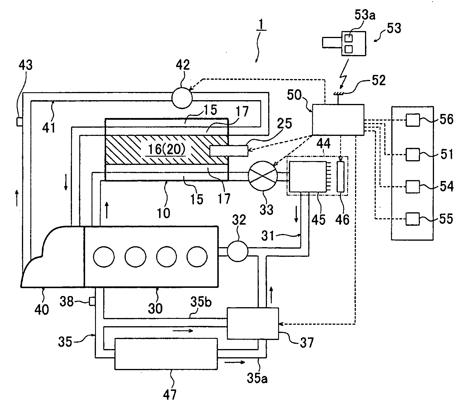
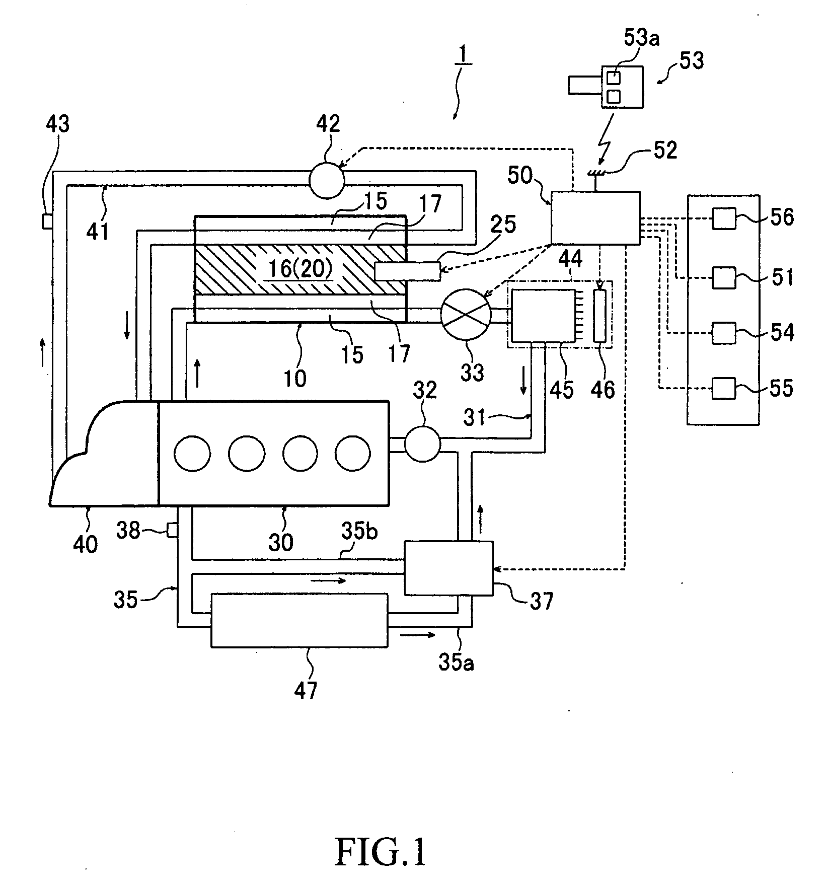
[0044]FIG. 1 is a schematic view showing a constituent example of a warming-up system for vehicle provided with a heat storage device according to a first embodiment of the present invention. A warming-up system for vehicle 1 includes a heat storage device 10, a cooling water circuit (first heat transfer medium circuit) 31 and a hydraulic circuit (second heat transfer medium circuit) 41. The heat storage device 10 has a heat storage medium (heat storage element) 20. The cooling water circuit 31 causes cooling water (LLC: long life coolant, first heat transfer medium) for an engine (first warming-up target) 30 to circulate through the heat storage device 10 and a heater core 45 of an in-vehicle heating apparatus 44. The hydraulic circuit 41 causes hydraulic oil (ATF: automatic transmission fluid, second heat transfer medium) for an automatic transmission (AT, second warming-up target) 40 to circulate through the heat storage device 10. The cooling water circuit 31 is derived from a w...

second embodiment

[0073]Next, a warming-up system for vehicle according to a second embodiment of the present invention will be described. In this regard, in explanation for a second embodiment and corresponding drawings, the same reference numerals are assigned to components (constituent parts) similar to or corresponding to those in the first embodiment, and detailed explanation for the components is omitted below. Further, matter other than the matter that will be described below and matter shown in the drawings are similar to those in the first embodiment.

[0074]FIG. 14 is a schematic view showing a constituent example of a warming-up system for vehicle 1-2 of the second embodiment. In the first embodiment described above, the heater core 45 of the heating apparatus 44 has been placed at the downstream side of the heat storage device 10 in the cooling water circuit 31. However, in this second embodiment, another heat storage device 10-2 having a structure in which the heater core 45 and the heat s...


PUM


Abstract

A warming-up system for vehicle includes: a heat storage device having a heat storage element; a first heat transfer medium circuit for causing a first heat transfer medium to circulate through the heat storage device; and a second heat transfer medium circuit for causing a second heat transfer medium to circulate through the heat storage device. The first and second heat transfer mediums flow into first and second warming-up targets, respectively. The heat storage device includes a first chamber in communication with the first heat transfer medium circuit, a second chamber in which the heat storage element is arranged, and a third chamber in communication with the second heat transfer medium circuit. Heat exchange can be carried out among the first heat transfer medium of the first chamber, the heat storage element of the second chamber and the second heat transfer medium of the third chamber.

Description

CROSS-REFERENCE TO RELATED APPLICATION[0001]The present disclosure relates to subject matter contained in Japanese Patent Application No. 2008-071037, filed on Mar. 19, 2008, the disclosure of which is expressly incorporated herein by reference in its entirety.BACKGROUND OF THE INVENTION[0002]1. Field of the Invention[0003]The present invention relates to a warming-up system for vehicle provided with a heat storage device capable of carrying out early warming-up of an internal combustion engine, a transmission and the like or immediate heating of an inside of a vehicle.[0004]2. Description of the Related Art[0005]Heretofore, as shown in Japanese Patent Application Publication No. 10-71837 and 2002-39335 (hereinafter, respectively referred to as “Patent Document 1” and “Patent Document 2”), for example, it is known a warming-up system for vehicle provided with a heat storage device that carries out warming-up of an internal combustion engine (hereinafter, referred to as an “engine”) ...

Claims


Application Information

Patent Timeline
IPC IPC(8): B60H1/04F28D15/00
CPCF01P11/20F01P2011/205F01P2060/045F01P2060/08F02D2200/023F02D2200/0414F28F2215/06F28D1/0426F28D1/05383F28D20/021F28D20/028F28D2020/0013Y02E60/145F02N19/10Y02E60/14
Inventor KUDO, TOMOHIDEOHASHI, TATSUYUKIYATABE, FUMIOFUKUSHIMA, SHINYA
Owner HONDA MOTOR CO LTD
Why Eureka
Try Eureka