Smoke detector

a detector and smoke technology, applied in the field of smoke detectors, can solve the problems of clogging the filter with dust, taking a lot of time and expense to conduct maintenance work on the filter, etc., and achieve the effect of stably merging and increasing the flow rate of the branch par

Active Publication Date: 2009-09-24
NOHMI BOSAI LTD
View PDF6 Cites 19 Cited by
  • Summary
  • Abstract
  • Description
  • Claims
  • Application Information

AI Technical Summary

Benefits of technology

[0027]Accordingly, the pressure loss of the flow at the branch part having the smoke detection part can be reduced, and hence the flow rate of the branch part flow can be increased. Further, the sampling air flow exhausted from the smoke detection part and the sampling air flow sucked by the fan can be stably merged.

Problems solved by technology

Further, in the conventional example, a part of the sampling air containing dust or the like is directly introduced into the airflow pipe, and passes through the filter, and hence there is a case in which a large amount of dust or the like is deposited on the filter, or the filter is clogged with the dust.
For that reason, the filter must be frequently cleaned or replaced, and hence it takes much time and expense to conduct maintenance work of the filter.

Method used


Image

  • Smoke detector
  • Smoke detector
  • Smoke detector

Examples


first embodiment

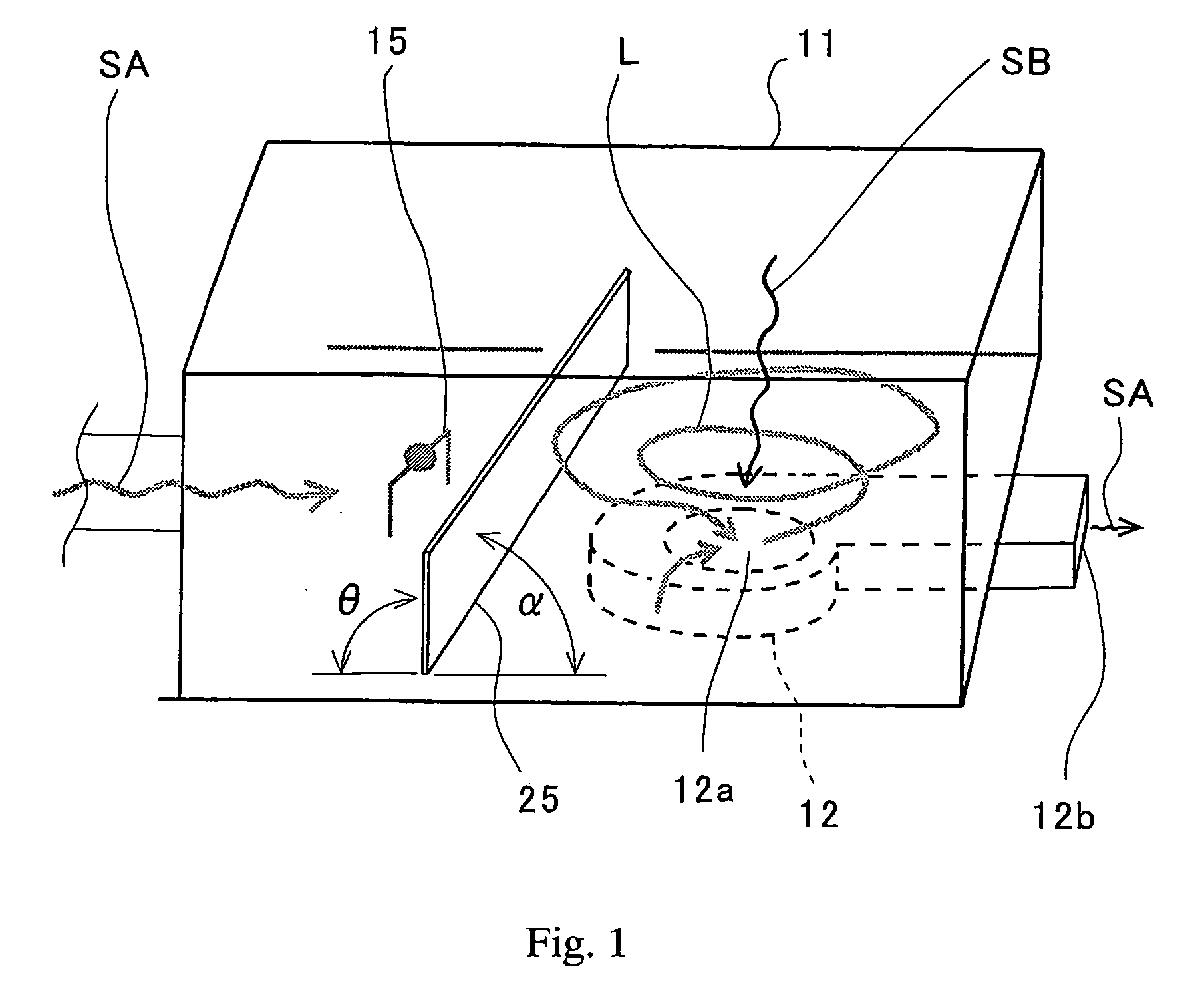
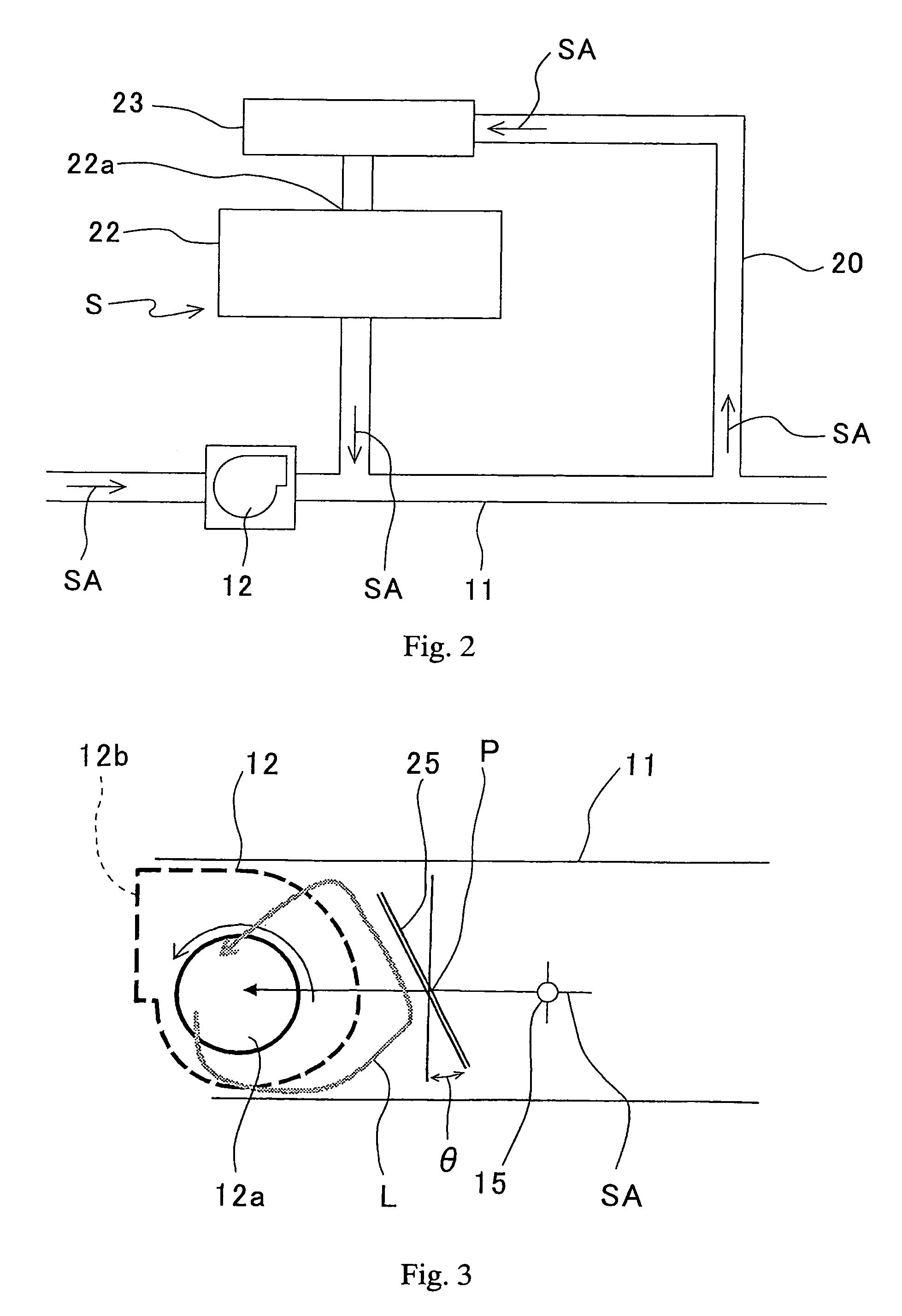
[0039]the present invention is described with reference to FIGS. 1 and 2.

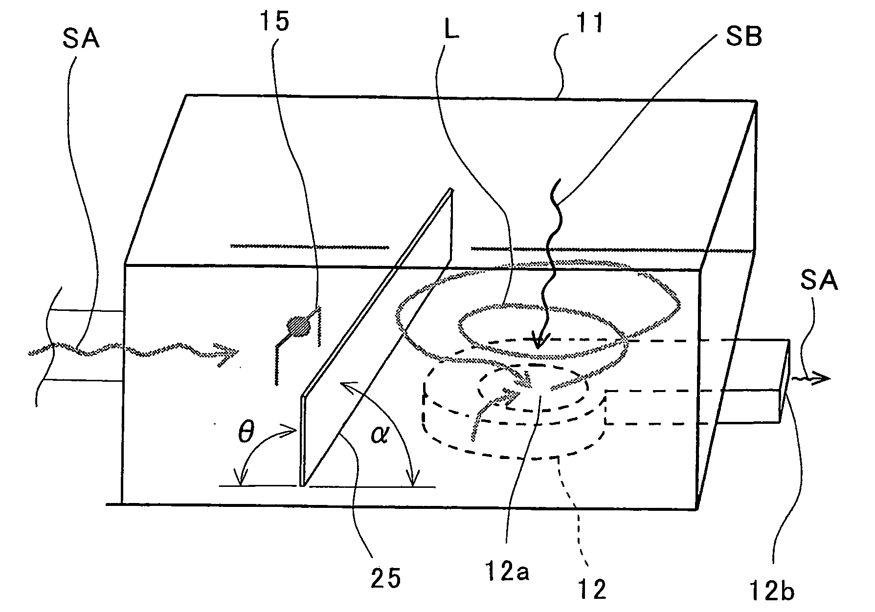
[0040]A smoke detector S includes a smoke detection part 22 connected to a sampling pipe 11 through a pipe 20, a filter 23 disposed at an inflow port 22a side of the smoke detection part 22, a fan (blower fan) 12 that sucks sampling air SA into the sampling pipe 11, and an air velocity sensor (flow sensor) 15 that measures an air velocity of the sampling air SA within the sampling pipe 11.

[0041]The smoke detection part 22 is provided with a light receiving element (smoke sensor) (not shown) such as a light emitting element and a photodiode, a light trap (not shown), a condenser lens (not shown), an aperture (not shown), and so on.

[0042]Within an inflow part 40 having a substantially box shape, and an intake port (not shown) for the sampling air arranged at a side surface thereof and a suction port 12a of the fan 12 arranged at a bottom surface thereof, an airflow direction of the sampling air SA at a primary si...

second embodiment

[0049]the present invention is described with reference to FIG. 3, and the same reference symbols of those of FIGS. 1 and 2 are also identical in the name and function.

[0050]A difference between the second embodiment and the first embodiment resides in that the straightening vane 25 is rotatably supported on the bottom surface or the ceiling surface of the inflow part 40 by a support shaft p. With the above-mentioned configuration, the straightening vane 25 can be set to the angle θ having the most shielding effect with respect to the reverse flow L according to the rotation speed of the fan 12 or the output of the air velocity sensor 15, and hence smoke detection with high precision can be executed even when the air velocity frequently varies.

third embodiment

[0051]A third embodiment according to the second invention is described with reference to FIGS. 5 and 6.

[0052]As illustrated in FIG. 5, a smoke detector 101 includes a smoke detection unit 102 having a dark box 121, a fan 103 that feeds air (sampling air) SA to be detected to the smoke detection unit 102, a pipe 104 serving as an air passage, a light emitting element 111 disposed within the smoke detection unit 102, a light receiving element 112 such as a photodiode, an air flow sensor 113 that measures the flow rate of the air and the fan 103, a power supply part 114 that supplies a power to the air flow sensor 113, and a fire determination part 115 connected to the light receiving element 112.

[0053]A smoke detection part 125 is disposed in the center of the dark box 121 of the smoke detection unit 102, and the sampling air SA that has passed through the pipe 104 and filtered by the filter 105 is introduced into the smoke detection part 125. Reference numeral 123 denotes a light tr...


PUM


Abstract

To enable an air velocity of sampling air to be precisely measured, a smoke detector (S) includes: a smoke detection part (22) connected to a sampling pipe (11); a fan (12) that sucks sampling air (SA) into the sampling pipe; and an air velocity sensor (15) that measures an air velocity of the sampling air within the sampling pipe. The air velocity sensor (15) is disposed at a primary side of the fan (12), and a straightening vane (25) is disposed between the air velocity sensor (15) and a suction port (12a) of the fan (12).

Description

BACKGROUND OF THE INVENTION[0001]1. Field of the Invention[0002]The present invention relates to a smoke detector that optically detects a contaminant such as smoke caused by fire and floating in the air, and detects the fire.[0003]2. Description of the Related Art[0004]A smoke detector is used for preventing fire or as a detecting system at a time of generation of the smoke or in a semiconductor manufacturing plant or a food factory requiring a certain level of environmental conservation.[0005]The conventional smoke detector includes a smoke detection part connected to a sampling pipe, a fan that sucks sampling air into the sampling pipe, and a wind velocity sensor that measures a wind velocity of the sampling air within the sampling pipe (for example, refer to JP 3714926 B).[0006]In the smoke detector, the sampling air flowing within the sampling pipe is partially introduced into the smoke detection part, and smoke detection is executed by a smoke sensor of the smoke detection par...

Claims


Application Information

Patent Timeline
Patent Type & Authority Applications(United States)
IPC IPC(8): G08B17/10
CPCG08B17/10G08B17/113Y10T137/87571A62C37/08G01N1/22G01N21/53G08B17/107
Inventor YOKOTA, HIROYUKI
Owner NOHMI BOSAI LTD
Why Eureka
Try Eureka