Optical unit and measuring instrument

a technology of optical units and measuring instruments, applied in the direction of instruments, mountings, measurement devices, etc., can solve the problems of limited mechanical accuracy of the slide mechanism and the turret mechanism, and inability to achieve high-quality measuremen

Inactive Publication Date: 2009-09-24
MITUTOYO CORP
View PDF4 Cites 3 Cited by
  • Summary
  • Abstract
  • Description
  • Claims
  • Application Information

AI Technical Summary

Benefits of technology

[0021]According to such an arrangement, an image measuring instrument and an optical measuring microscope that can achieve the above advantage can be provided.

Problems solved by technology

However, the conventional magnification switching methods have disadvantage as follows.
In the former lens switching method, the mechanical accuracy (including repeatability) of the slide mechanism and the turret mechanism is limited, so that optical axes of the imaging lenses 2A and 2B 1 are misaligned with the optical axis of the objective lens in switching the magnification.
Consequently, the focal position is not at the center of the imaging lens, so that a highly accurate measurement is not expected.
However, the optical path requires to be branched by the half mirrors 4 and 5, resulting in decrease in light quantity.
In addition, an imaging device such as a camera requires to be arranged correspondingly to each of the imaging lenses 2A and 2B, resulting in a large economic burden.

Method used


Image

  • Optical unit and measuring instrument
  • Optical unit and measuring instrument
  • Optical unit and measuring instrument

Examples


embodiment

Advantage of Embodiment

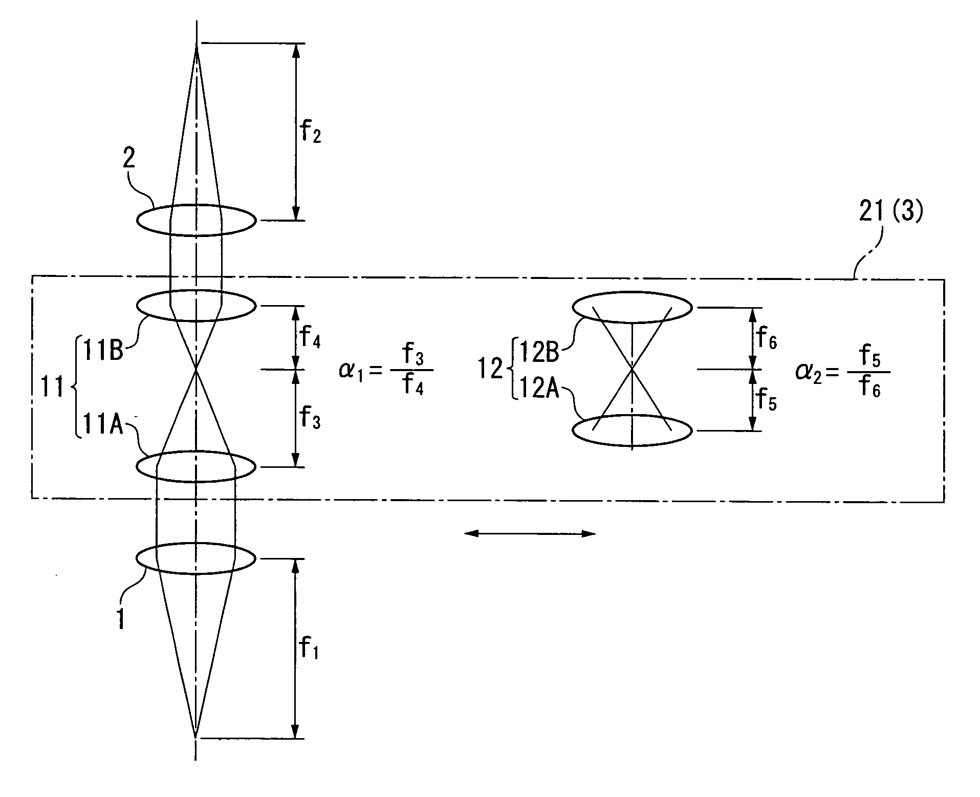
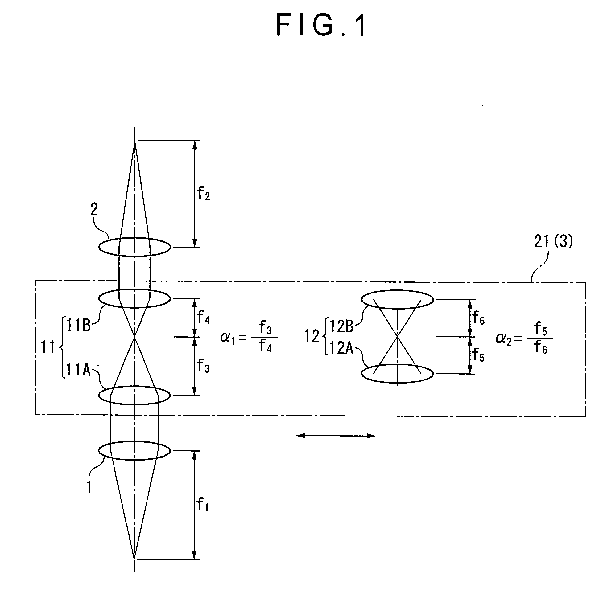
[0038]In the above embodiment, the first afocal optical system 11 and the second optical system 12, both of which have different magnifications, are arranged between the objective lens 1 and the imaging lens 2 with the switch 21 provided for shifting either one of the first afocal optical system 11 and the second afocal optical system 12 into the optical axis of the objective lens 1. By switching operation with the switch 21 to shift either one of the first afocal optical system 11 and the second optical system 12 into the optical axis of the objective lens 1, the magnification can be switched.

[0039]Even if the optical axes of the afocal optical systems 11 and 12 are misaligned with the optical axes of the objective lens 1 and the imaging lens 2, parallel light beams from the afocal optical systems 11 and 12 always image at the center of the optical axis of the imaging lens 2, thereby minimizing a deviation of the focus from the center of the imaging lens. Acc...


PUM


Abstract

An optical unit includes: an objective lens; an imaging lens that is arranged in the optical axis of the objective lens and images a light beam output from the objective lens; a plurality of afocal optical systems that are arranged between the objective lens and the imaging lens and have different afocal magnifications; and a switch that shifts either one of the afocal optical systems to be aligned with the optical axis of the objective lens.

Description

BACKGROUND OF THE INVENTION[0001]1. Field of the Invention[0002]The present invention relates to an optical unit and a measuring instrument. Specifically, it relates to an optical unit and a measuring instrument that can change optical magnification.[0003]2. Description of Related Art[0004]Conventionally, various methods for changing optical magnification have been used in an image measuring instrument, an optical instrument and the like.[0005]An optical system that forms an image with the use of an objective lens 1 and an imaging lens 2 as shown in FIG. 3 is called an infinity-correction optical system. When a focal length of the objective lens 1 is f1 and a focal length of the imaging lens 2 is f2, optical magnification β is expressed by the formula:β=f2 / f1When the focal length f1 of the objective lens 1 is fixed, the optical magnification β can be changed by changing the focal length f2 of the imaging lens 2.[0006]In order to change the focal length f2 of the imaging lens 2, a le...

Claims


Application Information

Patent Timeline
Patent Type & Authority Applications(United States)
IPC IPC(8): G01B11/27
CPCG02B15/04G02B7/02
Inventor SHIMOKAWA, SEIJINAGAHAMA, TATSUYAMORIUCHI, EISUKE
Owner MITUTOYO CORP
Why Eureka
Try Eureka