Blender container and cover

Active Publication Date: 2009-09-24
VITA MIX MANAGEMENT
View PDF81 Cites 23 Cited by
  • Summary
  • Abstract
  • Description
  • Claims
  • Application Information

AI Technical Summary

Benefits of technology

[0006]It is thus an object of one aspect of the present invention to provide a container for a blender which is shaped to provide efficient blending performance.
[0007]It is an object of another aspect of the present invention to provide a container, as above, in which the container itself is configured to assist in reducing the noise emanating from the blender.
[0008]It is an object of an additional aspect of the present invention to provide a container, as above, with a pouring spout that is located for more efficient pouring.

Problems solved by technology

As such, when the blended material is to be poured through the spout, it tends to congregate around the spout, and while some of that material will properly pass through the spout, some of it can also be misdirected past the sides of the spout.
At times, such can result in an unsatisfactory transfer of the material.
Attempts have been made to utilize the cover of the container to also close the spout, but such attempts have not always proved successful.
Many blenders create a certain amount of noise which in some environments can be distracting.
It has also been found that the square or round configurations of the container do not provide the most efficient blending as the blender blade rotates near the bottom of the container.

Method used


Image

  • Blender container and cover
  • Blender container and cover
  • Blender container and cover

Examples


Embodiment Construction

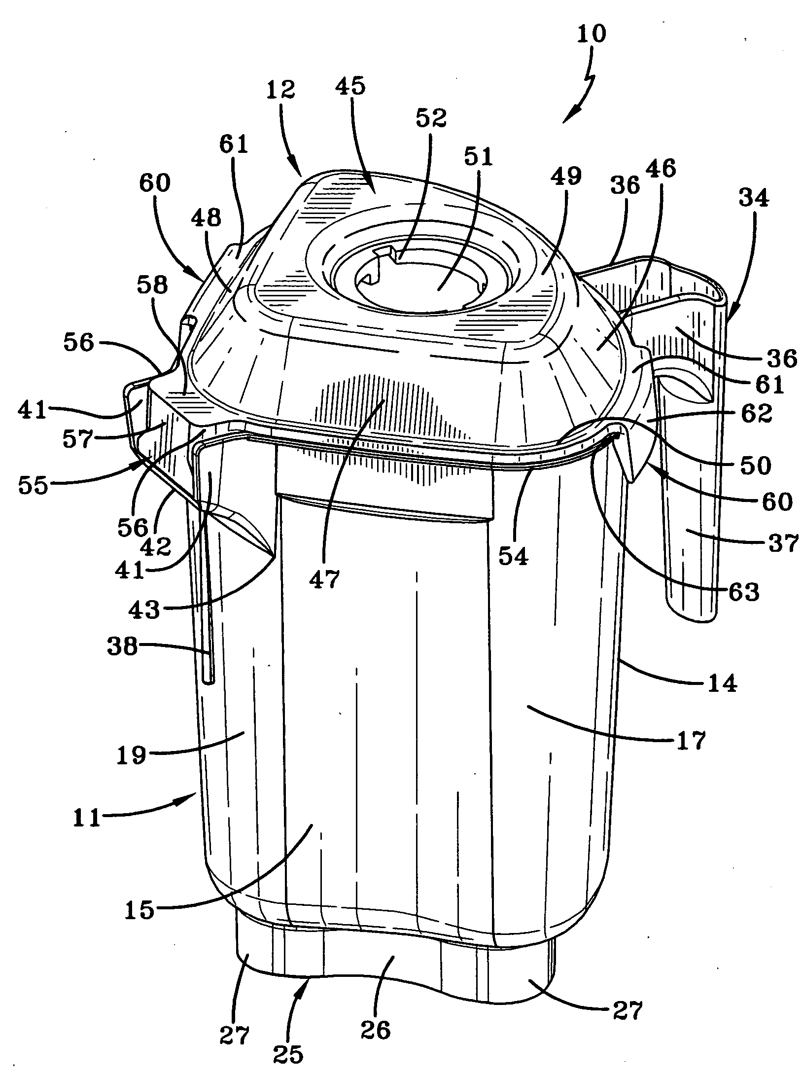
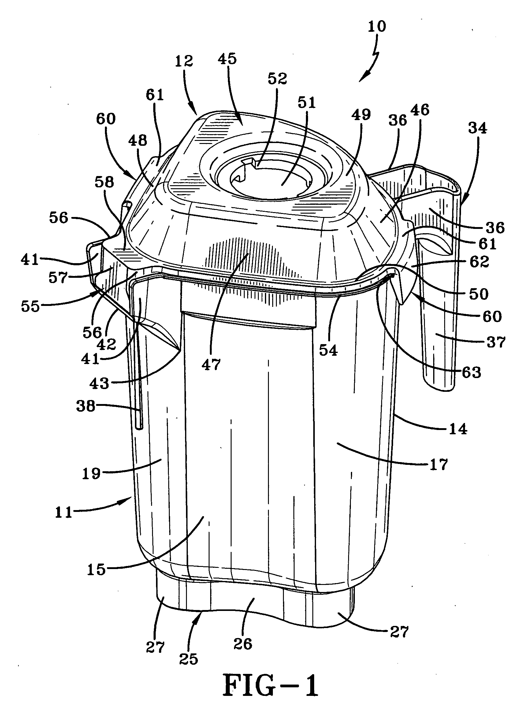
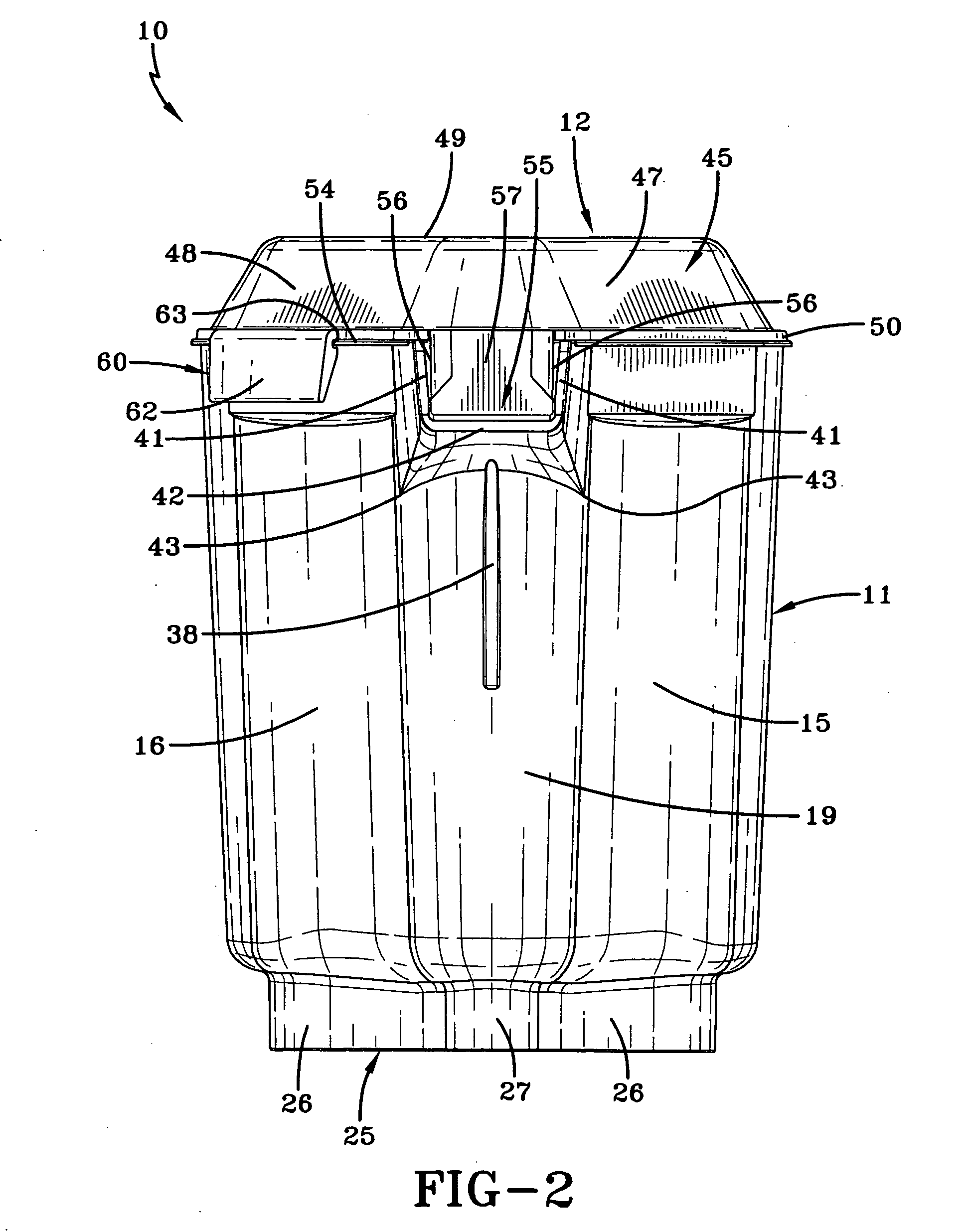
[0025]A blender container and cover assembly is indicated generally by the numeral 10 and includes a pitcher or container generally indicated by the numeral 11 and a lid or cover generally indicated by the numeral 12. Container 11 may be made of any suitable rigid plastic material, such as a copolyester material, and cover 12 may be made of any suitable flexible material such as synthetic rubber.

[0026]Container 11 includes a bottom or base surface 13 having three sidewalls 14, 15, and 16 extending upwardly from the periphery thereof. Sidewall 14 is arcuate in nature being formed as one continuous curve or arc, while sidewalls 15 and 16 are generally straight. Sidewall 14 intersects sidewall 15 at a radiused corner 17 and intersects sidewall 16 at a radiused corner 18. Straight sidewalls 15 and 16 intersect each other at a radiused corner 19. As shown in FIG. 6, container base surface 13 is preferably generally flat. However, as shown in FIG. 6A, base surface 13 can be sloped downwar...


PUM


Abstract

A container (11) for a blender includes a base surface (13) and a blade (20) which is rotatable on an axis above the base surface (13). An arcuate wall (14) and two generally straight walls (15, 16) extend upwardly from the base surface (13) and terminate at the upper end of container (11). The axis of rotation of the blade (20) is closer to the arcuate wall (14) than it is to the generally straight walls (15, 16). A skirt (25) extends downwardly from the base surface (13) and has an opening. Sound baffling fingers (32) extend from the skirt (25) and into the opening. A spout (40) is formed at the intersection of two of the walls (14, 15, 16), the spout (40) having an entry point located approximately twenty to thirty percent of the height of the walls (14, 15, 16) from the upper end of the container (11). A handle (34) is positioned opposite to the spout (40) and a cover (12) includes a plug (55) to close the spout (40).

Description

TECHNICAL FIELD[0001]This invention relates to a container and cover for use with a blender. More particularly, this invention relates to a container which is shaped to efficiently blend materials therein and which can easily discharge those materials through a pouring spout that is closed by the cover during blending operations.BACKGROUND ART[0002]Traditional containers for a blender have most often been generally round or square in configuration with at least some of these containers being provided with a pouring spout. That spout is usually positioned near the top of one of the sidewalls or a corner of the container at the rim thereof. As such, when the blended material is to be poured through the spout, it tends to congregate around the spout, and while some of that material will properly pass through the spout, some of it can also be misdirected past the sides of the spout. At times, such can result in an unsatisfactory transfer of the material.[0003]When the spout is not in us...

Claims


Application Information

Patent Timeline
IPC IPC(8): B01F13/00
CPCB01F15/00831A47J43/0727B01F35/51
Inventor ULANSKI, ROBERT M.
Owner VITA MIX MANAGEMENT
Why Eureka
Try Eureka