
Monitoring control channel in wireless communication system

a wireless communication system and control channel technology, applied in the field of wireless communication, can solve the problems of difficult detection of control information, increased number of blind decoding attempts, and inability to decode user data on a data channel, so as to reduce the overhead caused by blind decoding, reduce the number of detection attempts, and effectively monitor the downlink control channel

Active Publication Date: 2009-09-24
LG ELECTRONICS INC
View PDF3 Cites 150 Cited by
  • Summary
  • Abstract
  • Description
  • Claims
  • Application Information

AI Technical Summary

Benefits of technology

[0011]The present invention provides a method and apparatus of effectively monitoring a control channel.
[0022]A user equipment (UE) can effectively monitor a downlink control channel. A base station (BS) can effectively multiplex and transmit a plurality of control channels for carrying control information regarding a plurality of UEs. Therefore, the number of detection attempts depending on blind decoding for monitoring the downlink control channel can be reduced. An overhead caused by blind decoding is reduced, and a time for finding the downlink control channel required by the UE is reduced. A battery consumption of the UE is reduced, and overall system performance can be improved.

Problems solved by technology

If the UE does not correctly detect its control information from the plurality of pieces of multiplexed control information, the UE cannot decode user data on a data channel.
However, it may be difficult to detect the control information by using only simple blind decoding.
Consequently, the number of blind decoding attempts may be unexpectedly increased in a control region where control information is transmitted.
Battery consumption of the UE increases in proportion to the number of detection attempts.

Method used


Image

  • Monitoring control channel in wireless communication system
  • Monitoring control channel in wireless communication system
  • Monitoring control channel in wireless communication system

Examples


Embodiment Construction

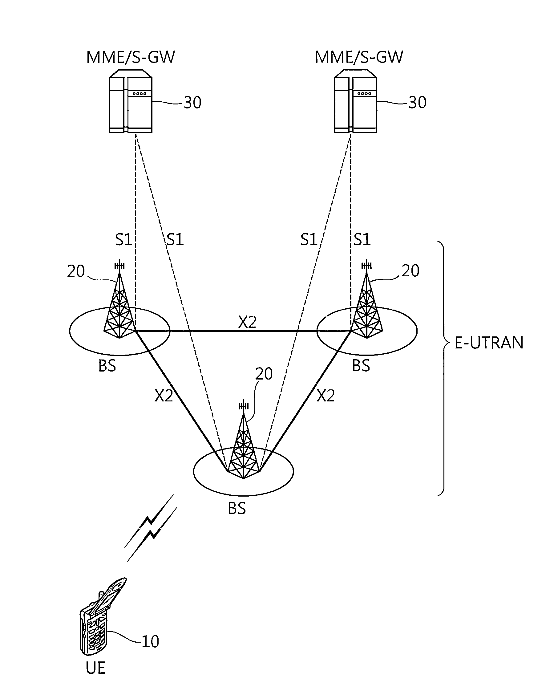
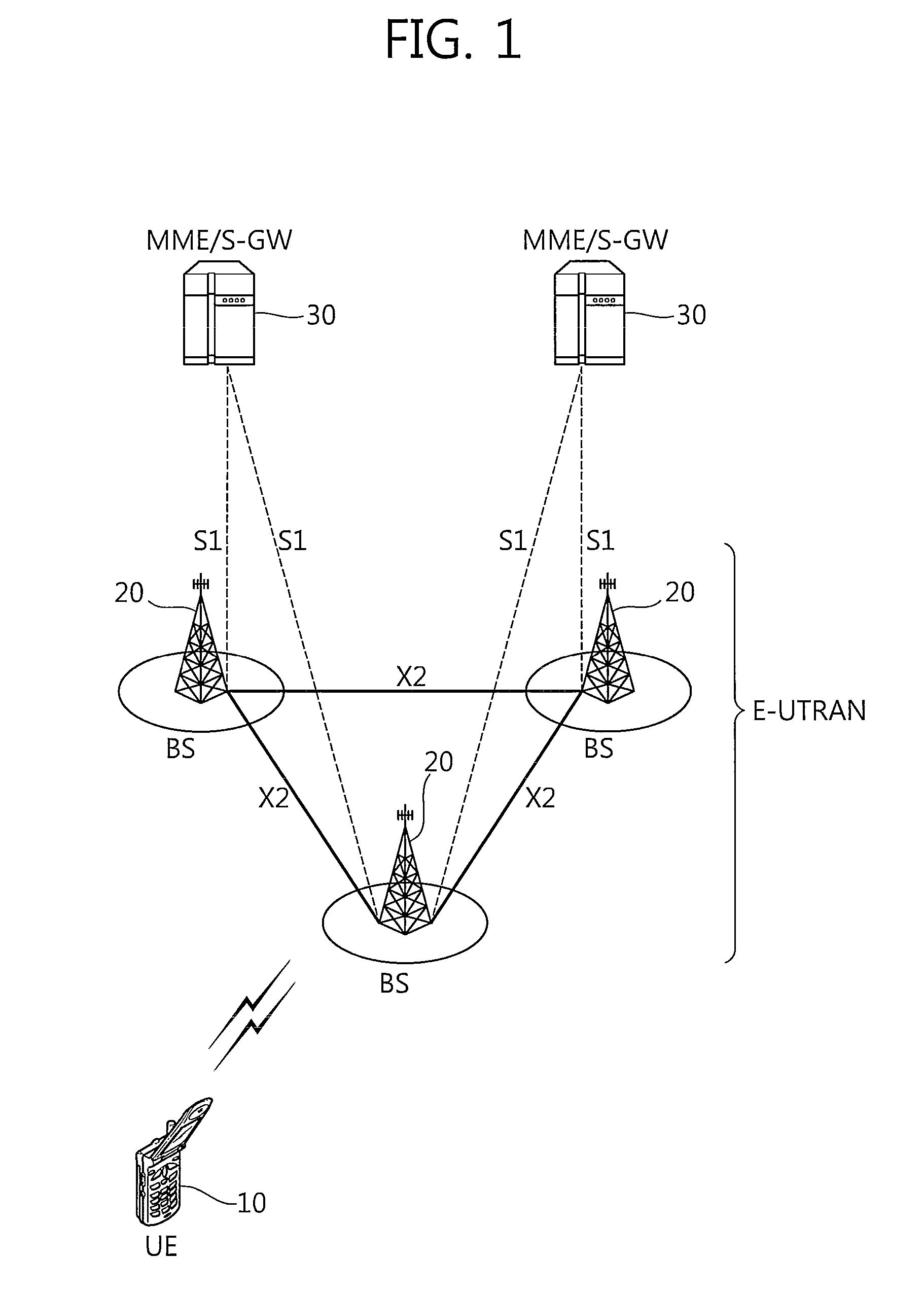
[0039]FIG. 1 shows a structure of a wireless communication system. The wireless communication system may have a network structure of an evolved-universal mobile telecommunications system (E-UMTS). The E-UMTS may be also referred to as a long term evolution (LTE) system. The wireless communication system can be widely deployed to provide a variety of communication services, such as voices, packet data, etc.

[0040]Referring to FIG. 1, an evolved-UMTS terrestrial radio access network (E-UTRAN) includes at least one base station (BS) 20 which provides a control plane and a user plane.

[0041]A user equipment (UE) 10 may be fixed or mobile, and may be referred to as another terminology, such as a mobile station (MS), a user terminal (UT), a subscriber station (SS), a wireless device, etc. The BS 20 is generally a fixed station that communicates with the UE 10 and may be referred to as another terminology, such as an evolved node-B (eNB), a base transceiver system (BTS), an access point, etc...


PUM


Abstract

A method and apparatus of monitoring a physical downlink control channel (PDCCH) is disclosed. A starting location of a search space in a control region of a subframe k is acquired. The search space is defined by a set of PDCCHs at each aggregation level. The set of PDCCHs from the starting location in the search space at the each aggregation level is monitored. The starting location is defined by the multiple of the aggregation level in the control region.

Description

CROSS-REFERENCE TO RELATED APPLICATIONS[0001]This application claims the benefit of priority of U.S. Provisional Application No. 61 / 038,056 filed on Mar. 20, 2008, U.S. Provisional Application No. 61 / 038,415 filed on Mar. 21, 2008, U.S. Provisional Application No. 61 / 039,112 filed on Mar. 25, 2008, and Korean Patent Application No. 10-2008-0083131 filed on Aug. 26, 2008, which are incorporated by reference in their entirety herein.BACKGROUND[0002]1. Field of the Invention[0003]The present invention relates to wireless communications, and more particularly, to a method and apparatus of monitoring a control channel to effectively detect control information.[0004]2. Related Art[0005]In a typical wireless communication system, a base station (BS) provides services to a plurality of user equipments (UEs). The BS schedules user data on the plurality of UEs, and transmits control information together with the user data. The control information contains scheduling information regarding the ...

Claims


Application Information

Patent Timeline
IPC IPC(8): H04L12/26
CPCH04L5/0091H04L27/2656H04L27/261H04L5/0053H04W24/00H04W48/12
Inventor KIM, SO YEONCHUNG, JAE HOON
Owner LG ELECTRONICS INC
Learn More