
Loudspeaker system and method for producing synthesized directional sound beam

a loudspeaker and directional sound technology, applied in the field of loudspeakers, can solve the problems of increasing system complexity and side lobe interference with the loudspeaker operator, and achieve the effects of extending the lower minimum operating frequency of the loudspeaker system, scalable transducer array size, and high acoustic power

Active Publication Date: 2009-09-24
MEYER SOUND LABORATORIES
View PDF20 Cites 20 Cited by
  • Summary
  • Abstract
  • Description
  • Claims
  • Application Information

AI Technical Summary

Benefits of technology

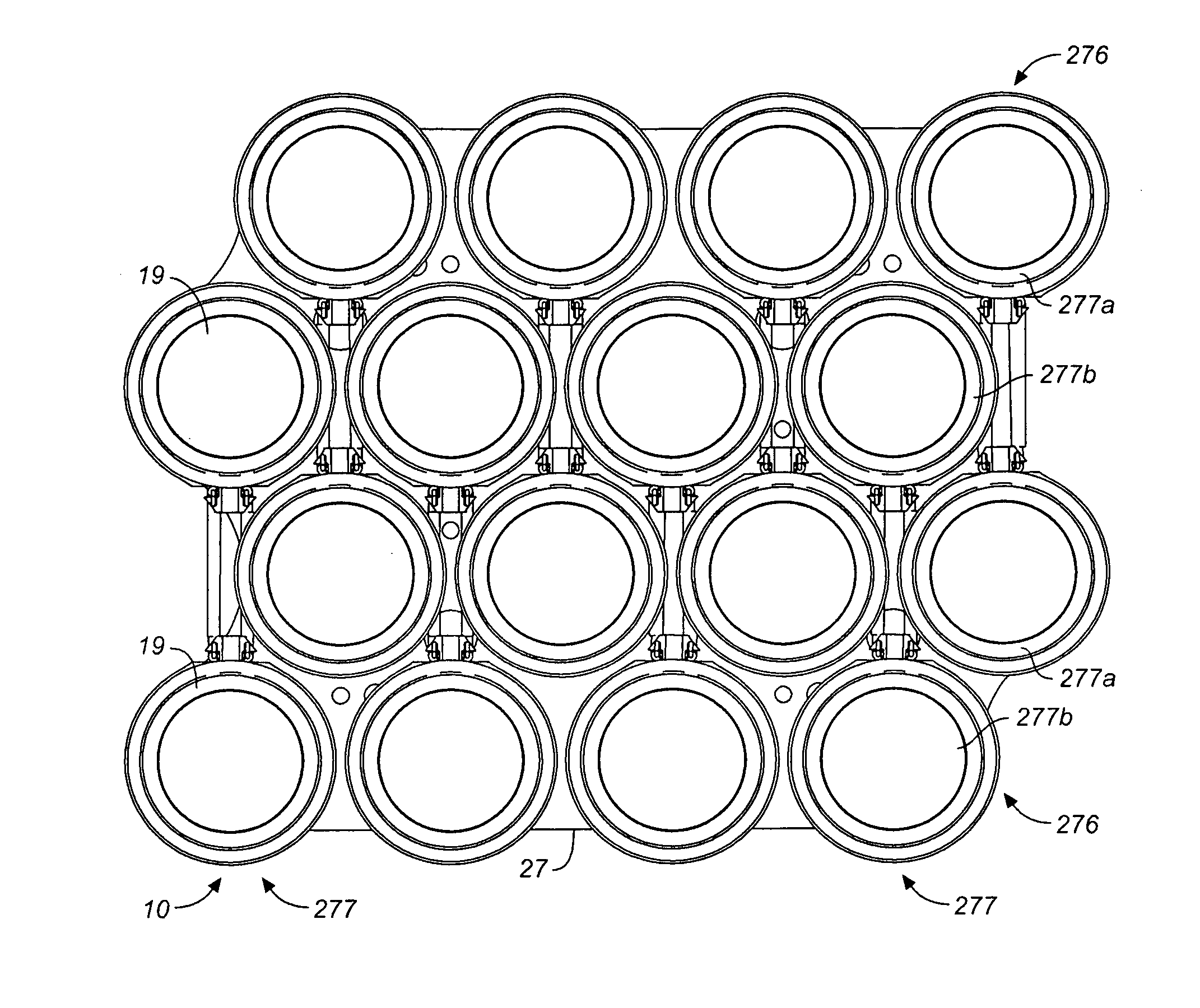
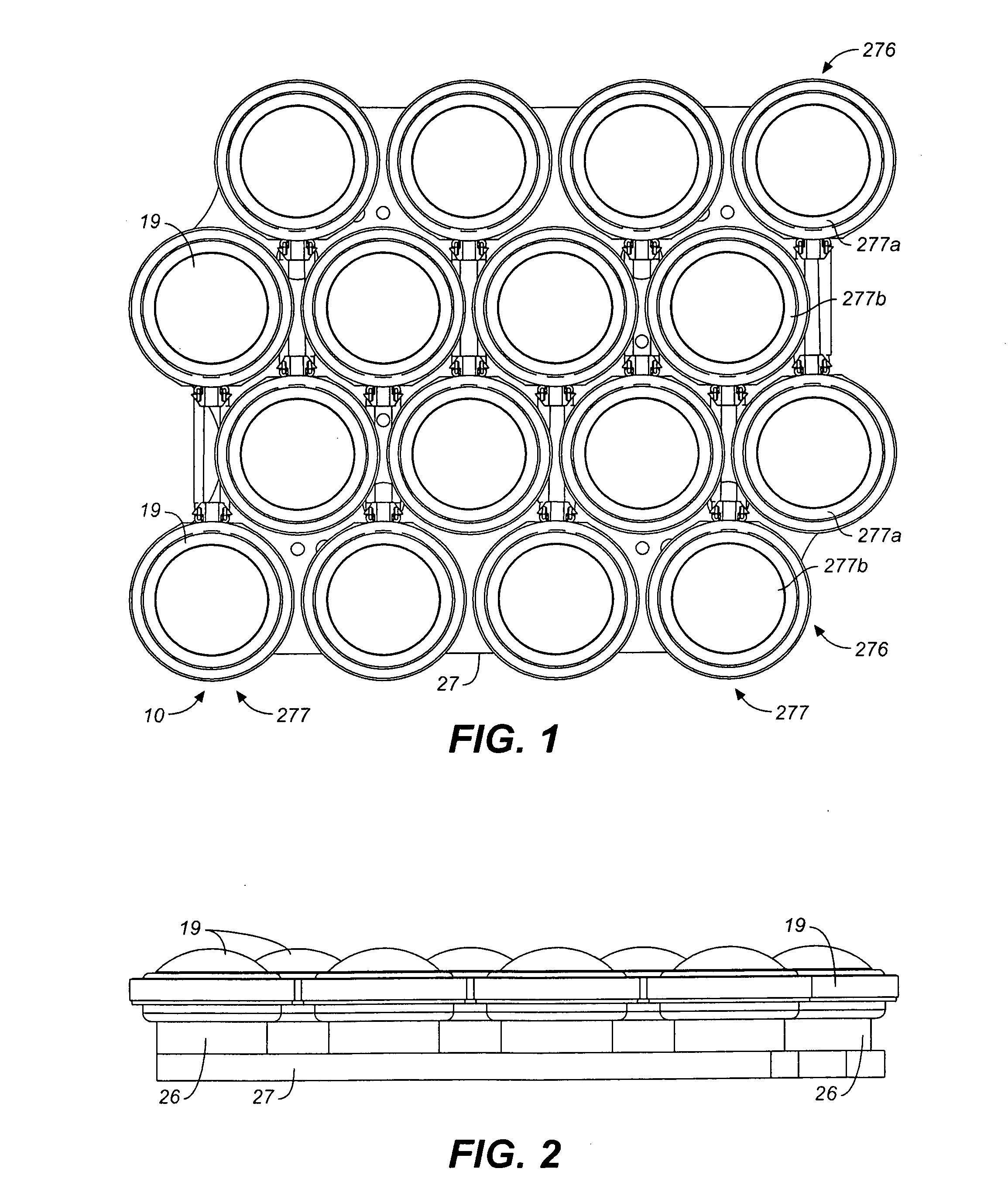
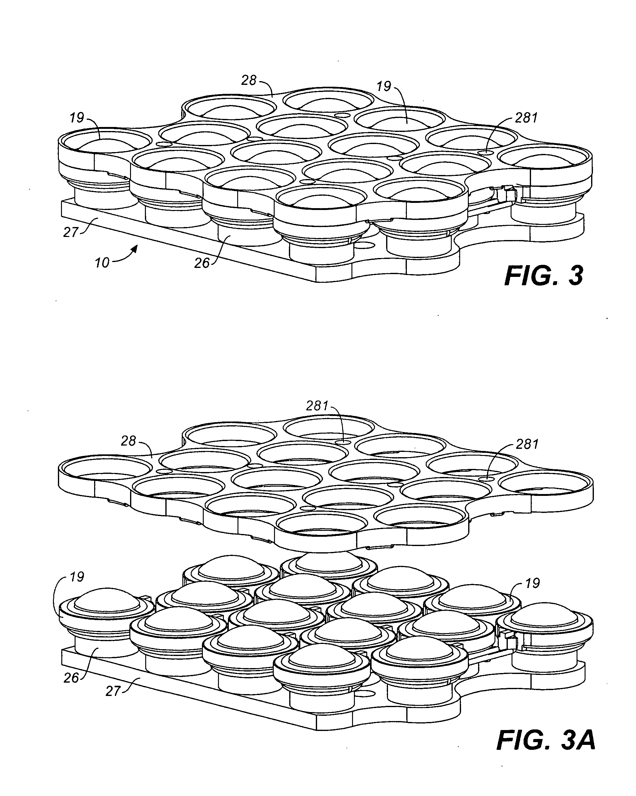
[0008]The present invention is directed to a loudspeaker system having a plurality of contiguous transducer elements configured in a closely spaced transducer array such that their acoustic outputs combine to produce a focused beam of sound in front of the array that is substantially uniform about its axis of radiation, that contains high acoustic power, and that maintains its beam form over the operating frequency range the loudspeaker system. The transducer array lies in a plane and has a perimeter that approximates a circle. The transducers of the array will substantially fill a circle that is tangent to the outmost transducers of the array. It is contemplated that, to achieve a desired beam form the fill-factor for the circle circumscribing the array should be at least approximately 70%. The size of the transducer array is scalable by increasing the number of transducers in the array. Enlarging the array will extend the lower minimum operating frequency of the loudspeaker system while maintaining control over beam width.
[0010]The loudspeaker system and method of the invention can provide a substantially uniform and focused beam of sound having a fixed polar pattern or a polar pattern that can be adjusted electronically by means of electronic signal processing. In the version with an adjustable polar pattern, the beam direction and / or beam shape can be electronically altered without the need to physically move loudspeaker or alter the loudspeaker's transducer elements or array. In the fixed beam version of the loudspeaker system only one signal processor is required to achieve a narrow beam width over a wide range of frequencies. Also, only one amplifier channel is required to power all the transducer elements, although several amplifiers can be used operating in a parallel to distribute the load of the transducer elements. Where electronic adjustability of the sound beam is desired, more than one, and most suitably several, signal processors and amplifiers are provided for separately powering the transducer elements or groups of transducer element in the transducer array. Such multi-channel signal processing would provide the capability of electronically altering the sound field in front of the transducer array, but would have the disadvantage of increasing the complexity of the system.
[0011]In either configuration of the invention (fixed or alterable sound field) side lobes of sound can be substantially attenuated or eliminated. This is a particular advantage in high power applications where people may be located close to the side of the loudspeaker. At very high sound pressure levels (SPL), side lobes could interfere with the operators of the loudspeaker.
[0013]In a preferred embodiment the loudspeaker system of the invention, the approximately circular array of closely spaced, relatively small transducers are mounted onto a surface such as a heat conductive base plate. Typically the surface is flat for ease of design and manufacture, but does not need to be flat to implement the invention. Non-flat surfaces, for example a curved plane, will produce different beam widths than a flat surface, which could be used to an advantage provided sufficient experimentation or modeling is used to predict and optimize the shape. A flat surface simplifies the design and required measurement, experimentation, and modeling to achieving a desired beam width at different frequencies and also allows the transducer element array to be scaled in size.
[0014]In a further and alternative aspect of the invention, the transducer element array of the loudspeaker system is constructed in relatively small transducer array modules that can be readily and operatively fitted together to produce larger arrays having a circular fill factor greater than approximately 70%. Use of smaller modules also advantageously allows the transducers to be grouped within the larger array and power to readily be provided to the different groups of transducers.

Problems solved by technology

Such multi-channel signal processing would provide the capability of electronically altering the sound field in front of the transducer array, but would have the disadvantage of increasing the complexity of the system.
At very high sound pressure levels (SPL), side lobes could interfere with the operators of the loudspeaker.

Method used


Image

  • Loudspeaker system and method for producing synthesized directional sound beam
  • Loudspeaker system and method for producing synthesized directional sound beam
  • Loudspeaker system and method for producing synthesized directional sound beam

Examples


Embodiment Construction

[0037]In the loudspeaker and loudspeaker system of the present invention, a desired substantially uniform beam form can be produced over a relatively wide operating frequency range from a plurality of transducer elements set in a transducer array configured, sized and powered as described herein. The beam form, whether fixed or adjustable, can be achieved substantially entirely through signal processing, with different beam forms being achievable for different applications. As used herein, “beam form” refers to the shape of the sound beam produced by a loudspeaker at any given frequency. (The term “polar pattern” is also used in the field of loudspeaker acoustics to describe a beam form.) The shape is the magnitude of the sound pressure measured spherically around the loudspeaker, and is typically plotted as a linear or log ratio to the main axis or strongest axis of sound beam. The total angle at which the sound pressure is either 3 dB or 6 dB weaker than the main axis is referred ...


PUM


Abstract

A loudspeaker system has a plurality of relatively small transducer elements configured in a closely spaced transducer array such that their acoustic outputs combine to produce a focused beam of sound in front of the array that is substantially uniform about the beams radiation axis. The transducer array lies in a plane and has a perimeter that approximates a circle, and will have fill-factor with respect to a circle circumscribing the array of at least approximately 70%. In one variation of the loudspeaker system, the transducer array is constructed in smaller transducer array modules that are operatively fitted together to produce a larger array.

Description

CROSS-REFERENCE TO RELATED APPLICATIONS[0001]This application claims the benefit of U.S. provisional patent application No. 61 / 062,945, filed Jan. 29, 2008, and is a continuation-in-part of U.S. patent application Ser. No. 11 / 641,549 filed Dec. 18, 2006, now pending.BACKGROUND OF THE INVENTION[0002]The present invention generally relates to loudspeakers used for sound reinforcement, and more particularly relates to loudspeakers capable of focusing a large amount of acoustic energy into a relatively narrow beam of intelligible sound that can be propagated over long distances.[0003]Long throw acoustical transmitting systems have been devised using parabolic dishes to focus the acoustic energy produced by a driving transducer positioned at the focal point of the parabolic dish. One such loudspeaker system is described in U.S. Pat. No. 5,821,470. This patent describes a system in which a parabolic dish reflects acoustic power produced by a high frequency horn loaded driver, and in which...

Claims


Application Information

Patent Timeline
IPC IPC(8): H04R25/00
CPCH04R1/403
Inventor MEYER, JOHN D.MEYER, PERRINSCHWENKE, ROGERRUBIO, ALEJANDRO ANTONIO GARCIAKOHUT, PAUL JOSEPHHERR, RICHARD D.ARNESON, JON M.SOPER, PETER C.
Owner MEYER SOUND LABORATORIES
Learn More