Refrigerant cycle device

Active Publication Date: 2009-10-01
DENSO CORP
View PDF9 Cites 80 Cited by
  • Summary
  • Abstract
  • Description
  • Claims
  • Application Information

AI Technical Summary

Benefits of technology

[0042]Thereby, the refrigerant flowing through the refrigerant bypass portion can be suppressed to be heated due to the environmental temperature, in which the refrigerant bypass portion is

Problems solved by technology

Thus, pressure loss of the refrigerant generated

Method used


Image

  • Refrigerant cycle device
  • Refrigerant cycle device
  • Refrigerant cycle device

Examples


first embodiment

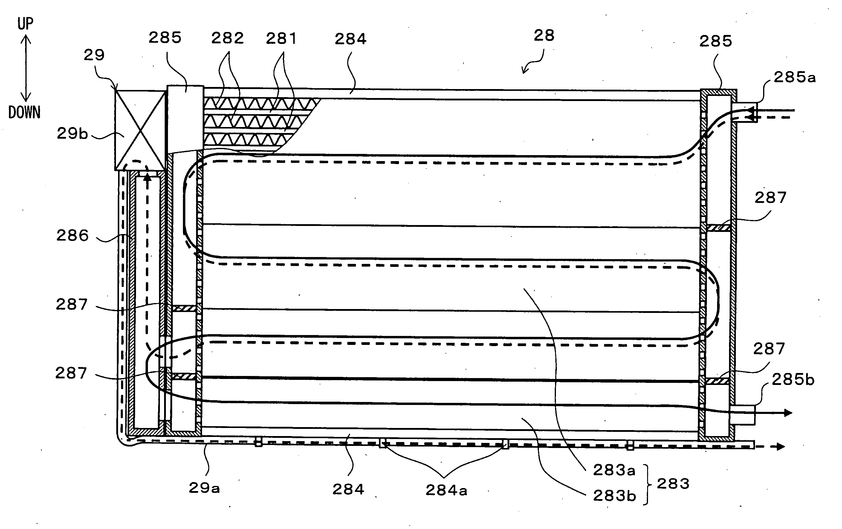
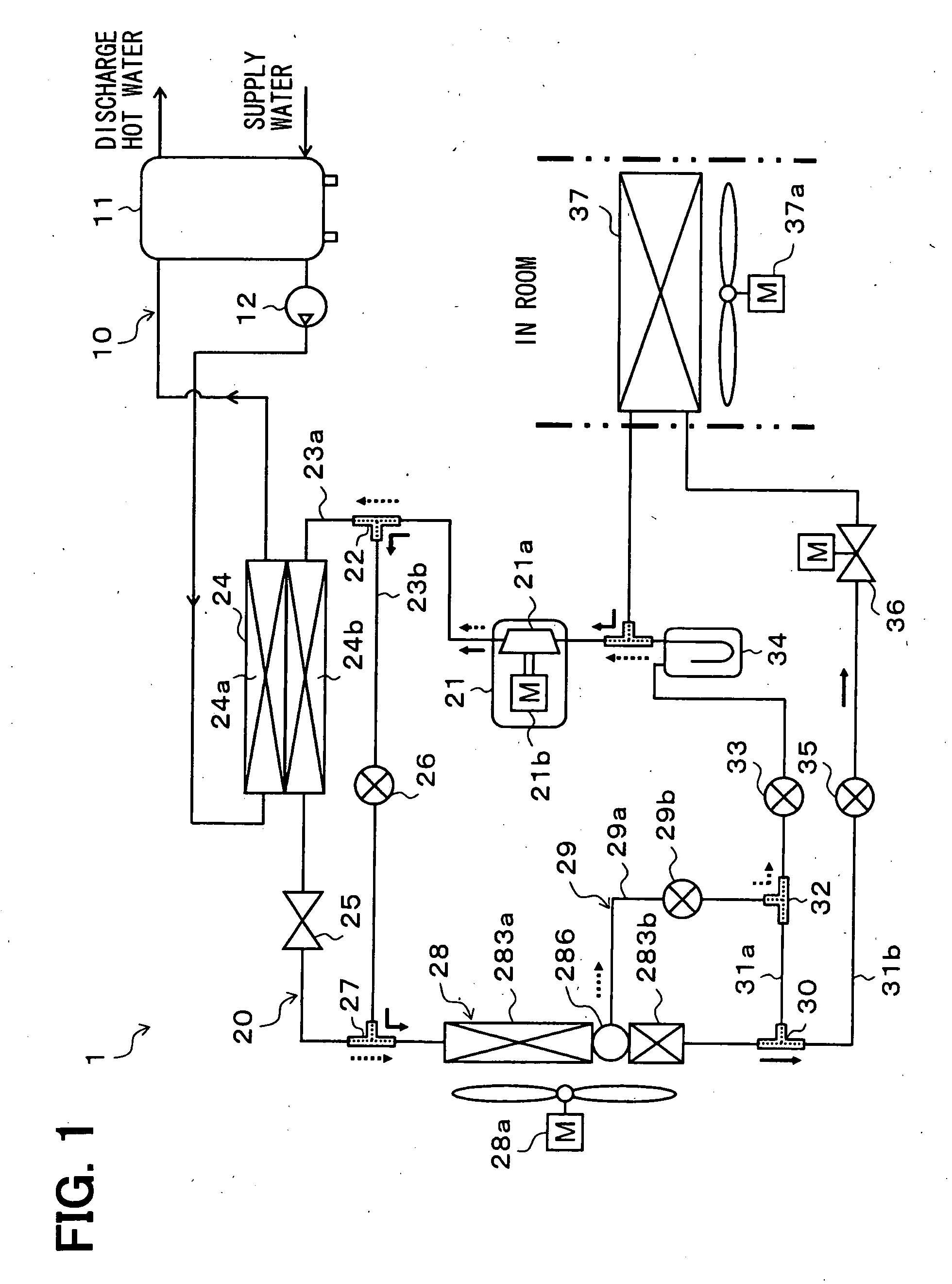
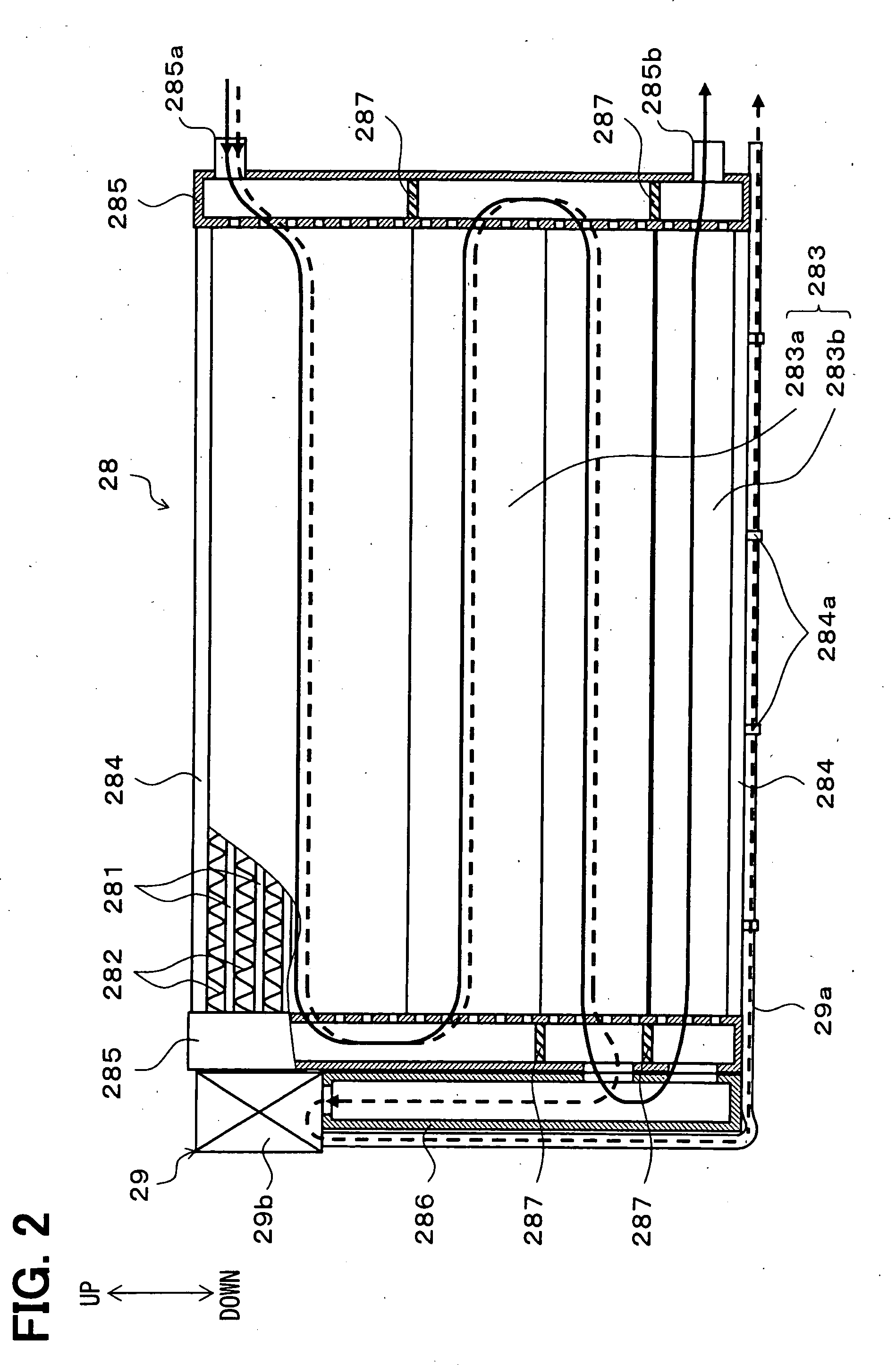
[0054]A first embodiment of the present invention will be described with reference to FIG. 1 and FIG. 2. In the present embodiment, a refrigerant cycle device 1 of the present invention is used for a room air conditioner and a water heater in a dwelling-house or the like. FIG. 1 is a schematic diagram showing a whole configuration of the refrigerant cycle device 1. In FIG. 1, solid arrows show a refrigerant flow in an air conditioner operation mode described below, and dashed arrows show the refrigerant flow in a hot water operation mode described below.

[0055]As shown in FIG. 1, the refrigerant cycle device 1 includes a water circuit 10, in which water stored in a hot water tank 11 is circulated, and a vapor compression refrigerant cycle 20 configured to be capable of switching a cooling operation mode, i.e., the air conditioner operation mode, for cooling a fluid to be heat exchanged and a heating operation mode, i.e., the hot water operation mode, for heating a fluid to be heat ex...

second embodiment

[0116]In the present embodiment, as shown in the whole configuration diagram of FIG. 3, a main pipe opening-closing valve 29c as a control valve for the refrigerant bypass device 29 is added with respect to the refrigerant cycle device 1 of the first embodiment. In the embodiments following the present embodiment, the same reference numeral is indicated for a portion which is the same with or equivalent to the portion described in the first embodiment, and the description thereof is skipped.

[0117]The main pipe opening-closing valve 29c is provided in a main pipe between an end portion of the bypass pipe 29a at a side of the second confluence portion 32 and the supercool heat exchange portion 283b, that is, in the main pipe connected between the second confluence portion 32 and the supercool heat exchange portion 283b, and is a solenoid valve for opening and closing the main pipe. Furthermore, the operation of the main pipe opening-closing valve 29c is controlled by the control volta...

third embodiment

[0121]Next, a third embodiment of the present invention will be described with reference to FIG. 4 and FIG. 5. In the present embodiment, a refrigerant cycle device 2 of the present invention is used for an air conditioning device for a room air conditioner. FIG. 4 is a schematic diagram showing a whole configuration of the refrigerant cycle device 2. In FIG. 4, solid arrows show a refrigerant flow in a cooling operation mode described below, and dashed arrows show the refrigerant flow in a dehumidification operation mode and a heating operation mode, which are described below.

[0122]The refrigerant cycle device 2 includes a vapor compression refrigerant cycle 40, which is configured to be capable of switching the cooling operation mode for cooling an indoor blowing air that is a fluid to be heat exchanged, and the heating operation mode or the dehumidification operation mode for heating the indoor blowing air and the like.

[0123]In the refrigerant cycle 40, a refrigerant discharge si...


PUM


Abstract

A subcool condenser having a condensation heat exchange portion, a receive portion and a supercool heat exchange portion is used as an outdoor heat exchanger that functions as a radiator in a cooling operation mode so that COP in the cooling operation mode is increased. In contrast, in a heating operation mode, a refrigerant bypass device that causes the refrigerant to flow so as to bypass the supercool heat exchange portion is provided so that pressure loss generated in the refrigerant flowing through the outdoor heat exchanger is decreased. Thereby, driving force of a compressor can be decreased and COP in the heating operation mode can be improved.

Description

CROSS REFERENCE TO RELATED APPLICATION[0001]The present application is based on Japanese Patent Application No. 2008-083218 filed on Mar. 27, 2008, the disclosure of which is incorporated herein by reference.FIELD OF THE INVENTION[0002]The present invention relates to a refrigerant cycle device configured to be capable of switching a cooling operation mode for cooling a fluid to be heat exchanged and a heating operation mode for heating a fluid to be heat exchanged.BACKGROUND OF THE INVENTION[0003]A conventional refrigerant cycle device is configured to be capable of switching a cooling operation mode for a fluid to be heat exchanged and a heating operation mode for heating a fluid to be heat exchanged.[0004]For example, a refrigerant cycle device described in JP-A-2005-306300 is used for a vehicle air conditioner. The refrigerant cycle device includes a utilization side heat exchanger for exchanging heat between a refrigerant and air to be blown into a vehicle compartment as the fl...

Claims


Application Information

Patent Timeline
IPC IPC(8): F25B27/00F25B1/00B60H1/22B60H3/00
CPCB60H1/00335B60H1/00342F25B13/00F25B39/04F25B40/02F25B41/04Y02B30/72F25B2313/02741F25B2339/044F25B2339/047F25B2341/065F25B2400/0403F25B2400/0417F25B2313/02731Y02B30/70F25B41/34F25B41/24
Inventor IKEGAMI, MAKOTOOSHITANI, HIROSHITAKANO, YOSHIAKI
Owner DENSO CORP
Why Eureka
Try Eureka