Wafer Stage Having Function of Anti-Collision

a technology of anti-collision and wafer stage, which is applied in the direction of positioning apparatus, metal-working machine components, manufacturing tools, etc., can solve the problems of large damage and cost to themselves, large negative influence on production efficiency, and colliding and damage of cantilever bars and stages, and achieves simple structure, good elasticity, and increased damping force

Inactive Publication Date: 2015-10-29
SHANGHAI MICRO ELECTRONICS EQUIP (GRP) CO LTD +1
View PDF28 Cites 1 Cited by
  • Summary
  • Abstract
  • Description
  • Claims
  • Application Information

AI Technical Summary

Benefits of technology

[0008]In comparison with the prior art, the present invention has the following advantages: since the gasbags made of rubber have good elasticity, when collision occurs, the gas is squeezed, into adjacent two gasbags via the damping buffer element (i.e., the damping hole), and then into the gas circulation system. Therefore, the damping hole can locally change the flow area of the fluid to generate a pressure loss, achieving purposes such as throttling, pressure regulating, buffering, and anti-vibration. In the present invention, the damping hole has a simple structure of long slim hole. When the damping buffer element is in a state of stable laminar flow, the pressure difference between two ends of the damping buffer element is in a good proportional relation with the flow rate through the damping hole, which can effectively increase the damping force and buffer the bouncing force on collision in a maximized way, thus stopping the moving wafer stages promptly when collision occurs. Through the settings for the gas pressure of the gasbags and the parameters of the damping holes, the positioning precision for the two wafer stages can satisfy the requirements of the controlling system, thus the efficiency of production is improved since no zero setting is needed when collision occurs.

Problems solved by technology

Besides, when the two stages are exchanging or the controlling system fails, the two stages may collide, causing great damage and cost to themselves due to their complicated structures.
Further, when the two stages collide, they may bounce off from each other, in which case, the measuring system cannot operate before performing direction finding and zero-setting, which has a great negative influence on the efficiency of production.
However, if the controlling system fails, the cantilever bar, and then the stages, are collided and damaged, without any secondary protection.
As to the design, if the wafer stages are added at their peripheral with the anti-collision bars, proximity sensors and buffers etc., the stages may have an overly large size, and besides, for the device which has a higher requirement for the integration level, the complicatedness of the structure and the difficulty of design will be increased when adding a plurality of elements, parts and sensors thereto.

Method used


Image

  • Wafer Stage Having Function of Anti-Collision
  • Wafer Stage Having Function of Anti-Collision
  • Wafer Stage Having Function of Anti-Collision

Examples


Embodiment Construction

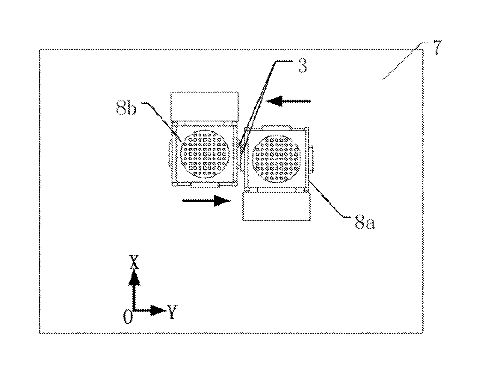
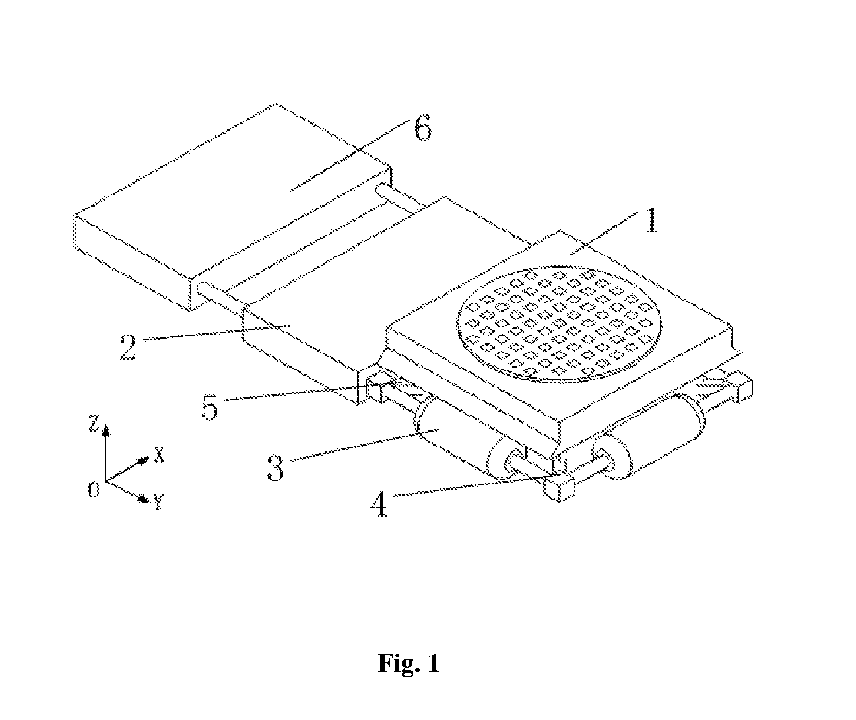
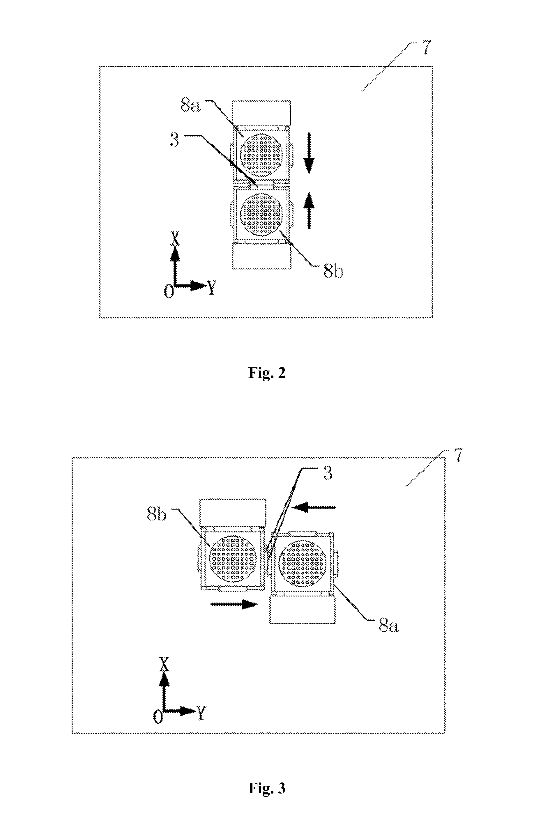
[0013]FIG. 1 illustrates the structure and principle of the wafer stage having function of anti-collision according to embodiments of the present invention. The wafer stage includes a body 1 and a cable stage 2 fixed on one side of the body. The wafer stage further includes three gasbags 3, four damping buffer elements 4 and a gas source 6. The gasbags are made of rubber. The three gasbags are arranged in series and are fixed on the other three sides of the body by an airbag support 5. Adjacent two gasbags have a damping buffer element therebetween to be in communication with a gas conduit which is fixed on the cable stage and in communication with the gas source 6. Each of the damping buffer elements preferably includes a plurality of long slim damping holes for throttling, which can locally change the flow area of the gas flow to generate a pressure loss, achieving purposes such as throttling, pressure regulating, buffering and anti-vibration, especially the long slim dampling hol...


PUM


Abstract

A silicon wafer platform with anti-collision function comprises a silicon wafer platform body (1) and a cable platform (2). The cable platform (2) is mounted on one side of the silicon wafer platform. The silicon wafer platform comprises three airbags (3), four damping buffer elements (4) and an air source (6), the three airbags (3) being connected in series and respectively secured on the other three sides of the silicon wafer platform by an airbag support (5), two adjacent airbags (3) communicating with a gas pipeline by one damping buffer element (4), and the gas pipeline being secured on the cable platform (2) and communicating with the air source. When two silicon platforms collide, the collision is buffered by the airbags and the silicon wafer platforms are not bounced off.

Description

TECHNICAL FIELD[0001]The present invention relates to a dual wafer stage switching system for a lithography machine, which can be applied into the lithography machine for semiconductor and belongs to the field of semiconductor manufacturing device.BACKGROUND ART[0002]In the magnetic suspending dual wafer stage switching system for a lithography machine, since the two wafer stages have no handspike or other limit structure, controlling the positions and postures of the wafer stages on the balancing block is completely depending on the position measurement by the sensors. Besides, when the two stages are exchanging or the controlling system fails, the two stages may collide, causing great damage and cost to themselves due to their complicated structures. Therefore, an anti-collision structure is crucial for wafer stages. Further, when the two stages collide, they may bounce off from each other, in which case, the measuring system cannot operate before performing direction finding and ...

Claims


Application Information

Patent Timeline
Patent Type & Authority Applications(United States)
IPC IPC(8): H01L21/673
CPCH01L21/67346
Inventor ZHU, YUZHANG, MINGLIU, ZHAOYANG, KAIMINGXU, DENGFENGTIAN, LIZHANG, LIQIN, HUICHAOWANG, PING ANYIN, WENSHENGHU, JINCHUNMU, HAIHUA
Owner SHANGHAI MICRO ELECTRONICS EQUIP (GRP) CO LTD
Why Eureka
Try Eureka