[0008]Accordingly, one aspect of the present invention is to allow the sequential defrost of individual evaporators (otherwise know as heat exchangers) while maintaining desired
airflow and design temperature in the cooling system. One example of the invention provides movable
doors or screens configured to unroll from a stored position to be placed over each
evaporator front and / or back side. In one example, the doors are controlled via a PLC and / or
frost detection devices. The controller directs the doors to move, for example, downward, into a closed position or upward into an open position. When these doors are closed, i.e., in an unrolled position, the heat exchanger is at least partially isolated from
air movement in the remainder of the freezer created by any fans that are often included with cooling systems, especially large-scale cooling systems. Thus, in this example,
airflow over the heat exchanger or heat exchangers undergoing defrost is reduced, and the heat exchangers will defrost more efficiently. Another aspect of the present invention is the containment of any heat produced in the
defrosting heat exchanger during the defrost process. This containment creates a
hot zone around the defrosting heat exchanger, which allows for a faster defrost time than some conventional defrosters. Additionally, the containment of the heat around the defrosting heat exchanger reduces the effect the defrosting heat exchanger on the area of the cooling system used to store items such as food.
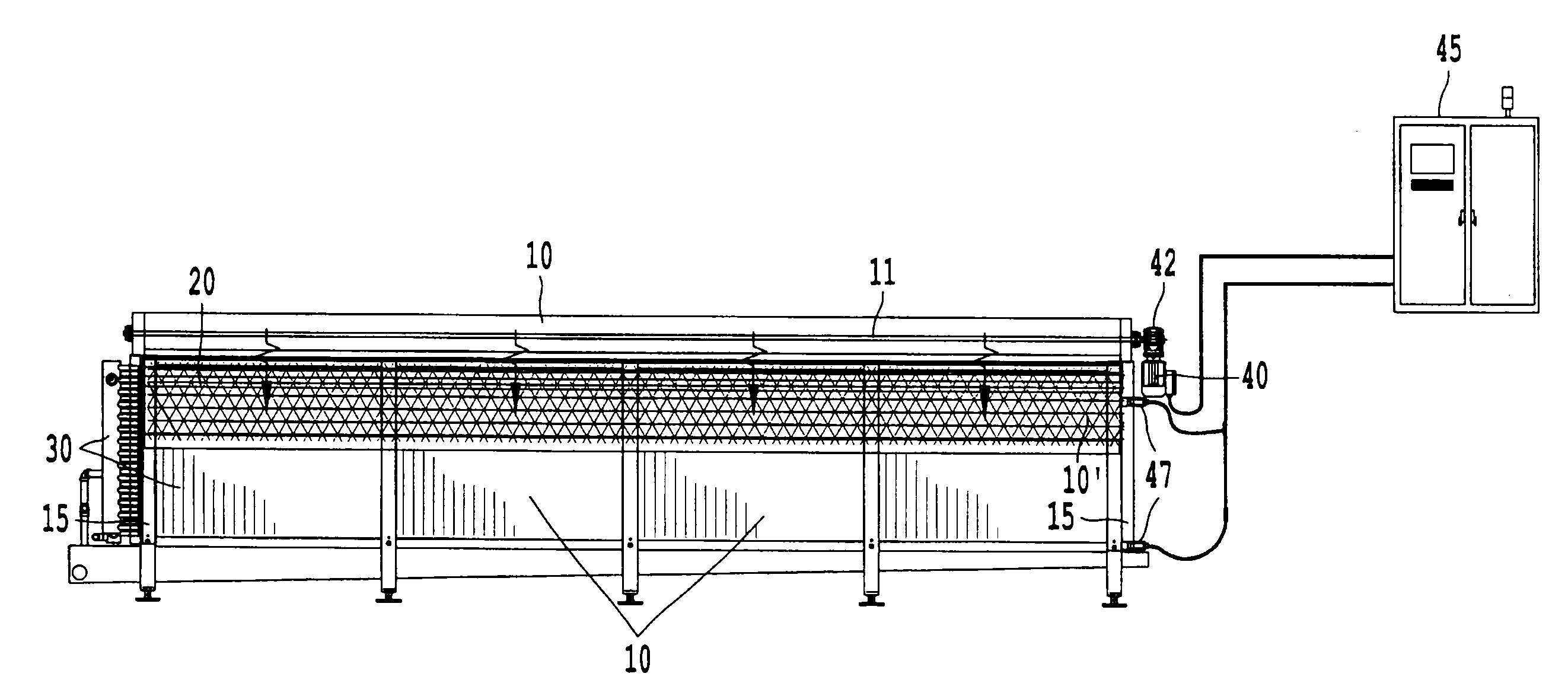
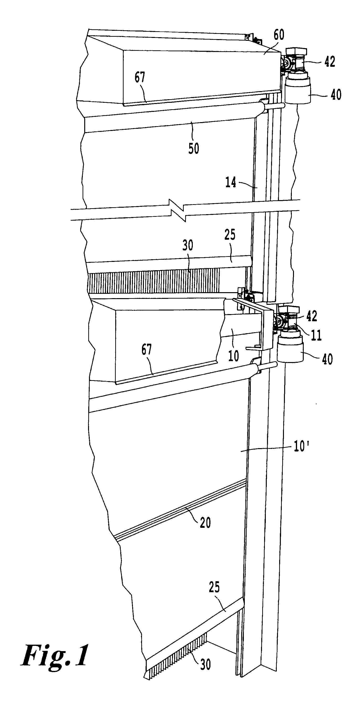
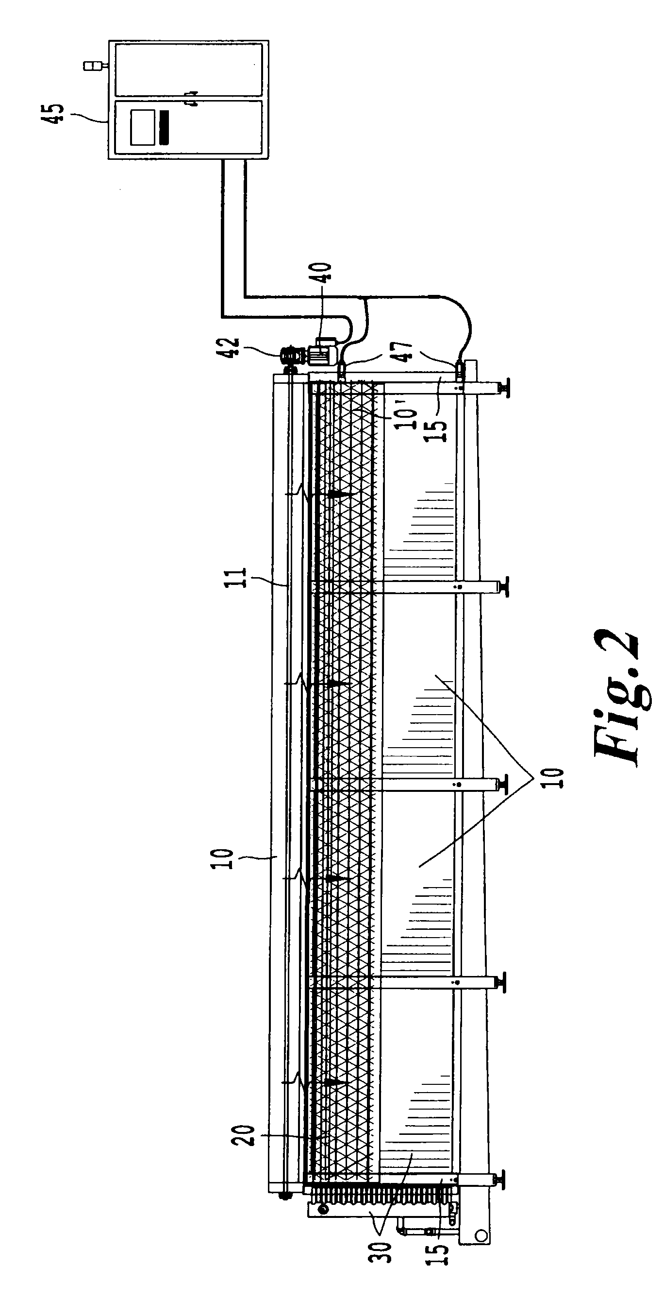
[0009]One aspect of the invention uses two doors on each heat exchanger, one on the front side of the heat exchanger and one on the back side of the heat exchanger. In one example, the doors are nylon fabric doors. The doors can be moved to roll or unroll by one or more motors. In an example using one motor, there may be a linkage to actuate the door on one side, typically the back side, of the heat exchanger. Preferably, any doors, shafts, and tracks are compatible with the temperatures normally present in the cooling system. In one example, the doors can be quite wide. In certain embodiments, when the doors are wide, the door preferably includes a reinforcement or “wind rib” in the center of the door to help prevent the door from collapsing due to
air movement within the cooling system.
[0010]One beneficial aspect of certain examples of the invention is the reduction in defrost time due to the concentration of heat used to defrost the heat exchangers. Another aspect of the invention is that the door or doors are can be placed in a rolled up (open position) or unrolled (closed position) within a hood, and thus, isolated from the freezer environment. Some aspects of the invention include a door with a weighted bar at the bottom. The weighted bar typically enhances the sealing effect of the door by pressing any sealing material against a sealing surface.
[0014]The door may be enclosed in a hood when in an open or rolled-up position. In one example, the hood is stainless steel or insulated
metal and encompasses most of the door when the door is in a rolled-up position. In one example, the only area exposed when the doors are in a rolled-up state is the bottom which remains outside of the hood area. The top of the hood can be pitched to drain
moisture which may be created during the pre-defrost of the door, and the hood can be heated to reduce the build-up of ice on the rolled up door during normal non-defrost operation of the cooling system.
[0016]Benefits of certain examples of the present invention include providing shorter defrost cycle times because the heat exchanger is more effectively isolated during the defrost cycle than are heat exchangers in conventional cooling systems. This isolation typically results in saving electrical usage. As the movable door typically takes of little space within the cooling system, another benefit of the present invention is improved
accessibility for cleaning and maintenance. The movable door can advantageously be retro-fit to existing systems, or installed in newly manufactured systems. One example of the present invention can provide a heat exchanger door system including a heat exchanger. The system further includes a first rotatable member,
proximate to the heat exchanger. The rotatable member is configured about an axis of rotation. A first door member is rolled around the rotatable member and can move from a rolled position to an unrolled position in which the first door member covers more of the heat exchanger than when the door member is in the rolled position. In one example, the rotatable member is coupled to a motor and, optionally, a gearbox. In a preferred example, the first door member is at least partially contained in a track and slides within the track during a roll-up or roll-down process. In some examples, the there are two rotatable members, each including a door member. In one variation of this example, the two rotatable members are disposed in parallel with each other.

