Two-dimensional code having rectangular region provided with specific patterns for specify cell positions and distinction from background

a two-dimensional code and rectangular region technology, applied in the field of two-dimensional codes, can solve problems such as large number of cells, and achieve the effect of increasing the number of cells

Active Publication Date: 2009-10-01
DENSO WAVE INC
View PDF4 Cites 55 Cited by
  • Summary
  • Abstract
  • Description
  • Claims
  • Application Information

AI Technical Summary

Benefits of technology

[0010]The present invention has been made in light of the issues described above, and has as its objects to provide a two-dimensional code which is able to make a good distinction between a background and a code region, suppress as much as possible the number of cell

Problems solved by technology

However, such a method needs a large number of cells that have to be allocated to the speci

Method used


Image

  • Two-dimensional code having rectangular region provided with specific patterns for specify cell positions and distinction from background
  • Two-dimensional code having rectangular region provided with specific patterns for specify cell positions and distinction from background
  • Two-dimensional code having rectangular region provided with specific patterns for specify cell positions and distinction from background

Examples


third embodiment

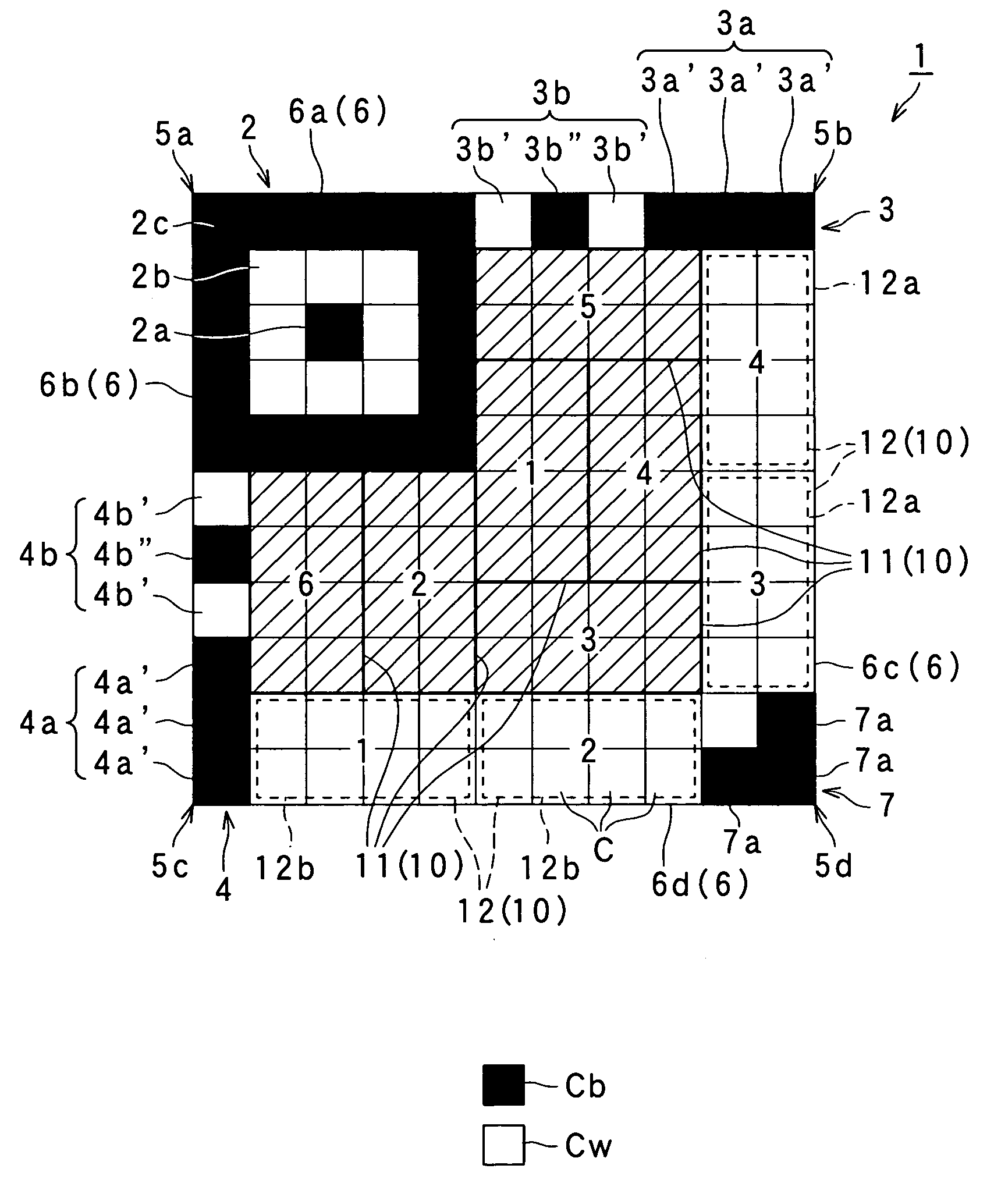
[0171]Hereinafter is described a third embodiment. FIG. 6 is a schematic explanatory view illustrating a 2D code 130, according to the third embodiment. FIG. 6 also omits a specific cell structure of each code block 10.

[0172]The third embodiment is different from the first embodiment in that each of second specific patterns 133, 134 has a structure different from that in the first embodiment, and that multi-color cells are used. Other portions of the configuration of the present embodiment are identical with those in the first embodiment. Accordingly, the following description will be mainly focused on the differences, and explanation will be omitted as to the identical portions of the configuration. In the example shown in FIG. 6, the configurations of the first specific pattern 2, the end pattern 7, the first borders 6a, 6b, and the second borders 6c , 6d are identical with those in the first embodiment. Also, the plurality of data code blocks 11 and the plurality of the error-cor...

fourth embodiment

[0183]Hereinafter will be described a fourth embodiment. FIG. 7 is a schematic explanatory view illustrating a 2D code 140, according to the fourth embodiment. FIG. 7 shows, by broken lines, the positions of error-correction code blocks 12, and also shows, by solid lines with hatching, the positions of the data code blocks 11. FIG. 7 omits a specific cell structure of each code block 10.

[0184]Similar to the first embodiment, the 2D code 140 of the present embodiment has a plurality of cells “C” (the reference symbol “C” is designated to only a portion of the cells in FIG. 7 and designation of the reference symbol to other cells is omitted) arranged in matrix. The 2D code 140 includes a plurality of code blocks 10, the first specific pattern 2 (having the same structure and functions as in the first embodiment), and second specific patterns 143, 144. The 2D code 140 of the present embodiment is configured to have a shape with square outline in which a plurality of cells “C” are arran...

fifth embodiment

[0216]Hereinafter will be described a fifth embodiment. FIG. 10 is a schematic explanatory view illustrating a 2D code 150, according to the fifth embodiment. FIG. 10 also shows, by broken lines, the positions of error-correction code blocks 12, and also shows, by solid lines with hatching, the positions of the data code blocks 11. FIG. 10 also omits a specific cell structure of each code block 10.

[0217]As shown in FIG. 10, the fifth embodiment is different from the first embodiment (shown in FIG. 1) in that the second specific patterns 3, 4 have been changed to second specific patterns 153, 154, and that blank cells (the cells between the first specific pattern 2 and the second specific pattern 153, and the cells between the first specific pattern 2 and the second specific pattern 154) are ensured to be used for other purposes. Other portions of the 2D code 150 are configured in the same manner as in the first embodiment. Accordingly, the following description will be focused on th...


PUM


Abstract

A two-dimensional code having a rectangular region is provided. In the rectangular region, there are code blocks composed of a plurality of cells, a first specific pattern specifying the positions of the cells, and a second specific pattern separating the code blocks from a background of the code. The first specific pattern is located at a specified corner of the rectangular region. The second specific pattern is located along one or more of first borders along which the first specific pattern is located, the first borders being part of the borders of the rectangular region. The code blocks include error-correction code blocks, which are located along second borders which are different from a border of the borders along which the second specific pattern is located. The second borders are part of the borders. Compressed data code blocks are also arranged in the same way as the error-correction code blocks.

Description

CROSS-REFERENCE TO RELATED APPLICATION[0001]This application is based on and claims the benefit of priorities from earlier Japanese Patent Application Nos. 2008-083486 and 2008-226472 filed Mar. 27 and Sep. 3, 2008, respectively, the descriptions of which are incorporated herein by reference.BACKGROUND OF THE INVENTION[0002]1. Technical Field of the Invention[0003]The present invention relates to a two-dimensional code, and in particular, to a two-dimensional code having a rectangular region delineated by a plurality of cells and formed to have specific patterns for specifying the positions of cells in the rectangular region and distinguishing the code from the background.[0004]2. Related Art[0005]Various types of two-dimensional codes (hereinafter also referred to as “2D code(s)”) have been supplied, in which a plurality of cells are arranged in a matrix. A typical reader (2D code reader) for reading such 2D codes is disclosed, for example, in Japanese Patent No. 2938338. The 2D co...

Claims


Application Information

Patent Timeline
IPC IPC(8): G06K19/06
CPCG06K19/06037G06K19/06075G06K19/06046
Inventor MIZUKOSHI, HIROAKITANAKA, MASAMIITO, YUICHIKITA, HAYATOUSHIJIMA, TAKAOHARA, MASAHIRO
Owner DENSO WAVE INC
Why Eureka
Try Eureka