Inkjet recording apparatus and method

a recording apparatus and inkjet technology, applied in the direction of inking apparatus, printing apparatus, other printing apparatus, etc., can solve the problems of difficult control of the modulus of elasticity, inability to stabilize the negative pressure characteristics of the pressure regulating chamber, uneven dimensional accuracy, etc., and achieve the effect of stably

Active Publication Date: 2009-10-01
FUJIFILM CORP
View PDF6 Cites 20 Cited by
  • Summary
  • Abstract
  • Description
  • Claims
  • Application Information

AI Technical Summary

Benefits of technology

[0022]According to the present invention, back pressure control, in which back pressure is

Problems solved by technology

However, it is necessary to devise a shape of the elastic deformation member, and unevenness in dimensional accuracy during production of the elastic deformation member may occur easily, which makes it difficult to control the modulus of elasticity.
Therefore there is a risk that it may not be possible to stabilize the negative pressure characteristics of the pressure regulating chamber.
Moreover, compactness is difficult to achieve since it is necessary to arrange the elastic deformation member directly above the recording head.
Furthermore, since the pressure of the gas inside the pressure regulating chamber container is regulated by causing deformation of the elastic deforma

Method used


Image

  • Inkjet recording apparatus and method
  • Inkjet recording apparatus and method
  • Inkjet recording apparatus and method

Examples


first embodiment

General Composition of Inkjet Recording Apparatus

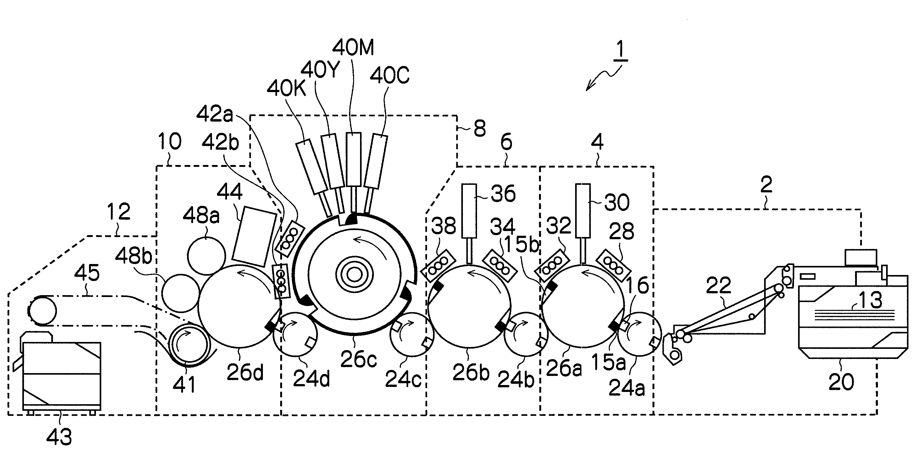
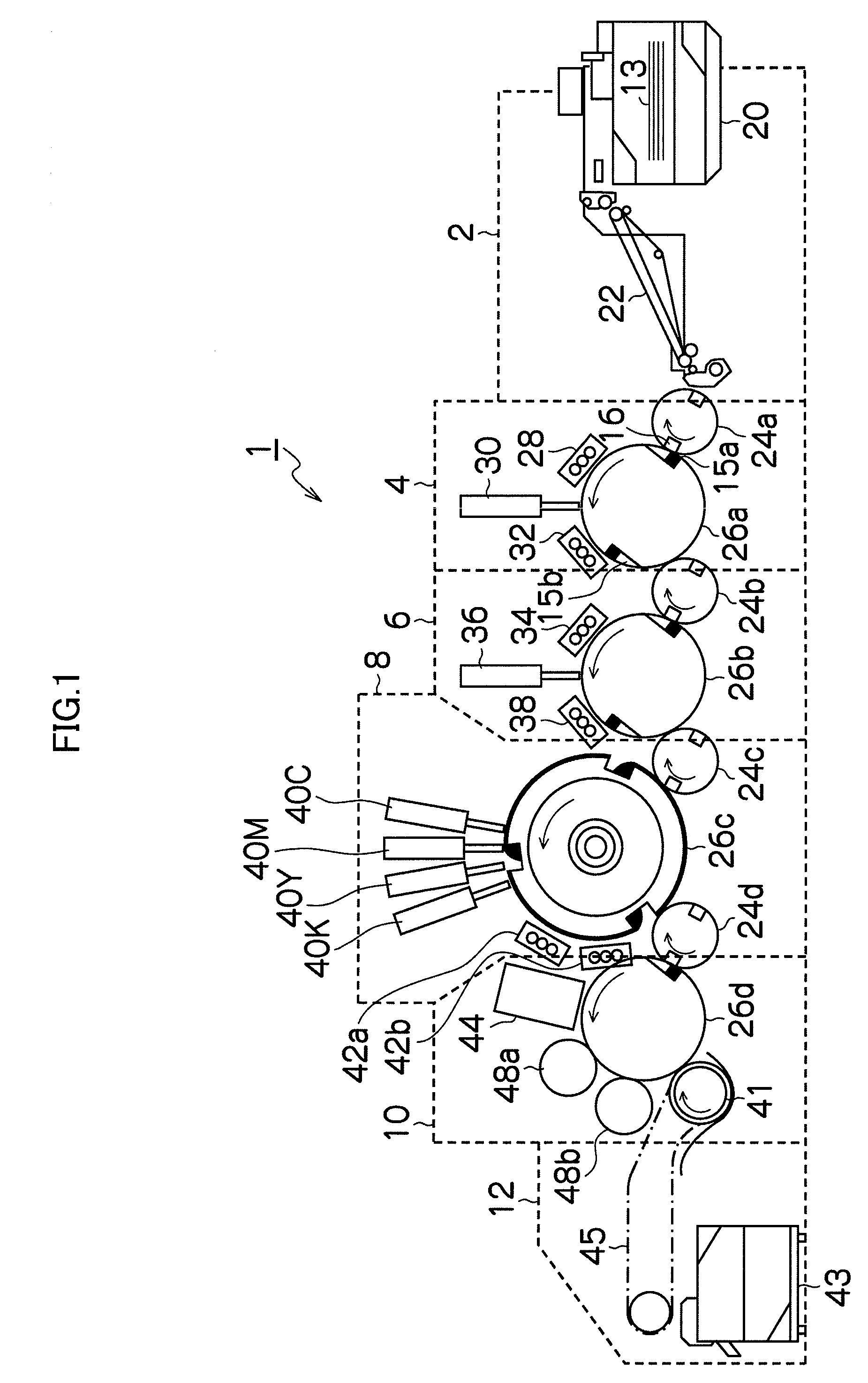
[0039]FIG. 1 is a general schematic drawing showing an inkjet recording apparatus 1 according to a first embodiment of the present invention. FIG. 1 shows the inkjet recording apparatus 1 of a drum conveyance type, in which paper 13 is held and conveyed on circumferential surfaces of drum-shaped conveyance members, as an embodiment of the inkjet recording apparatus according to the present invention. The inkjet recording apparatus according to the present invention is not limited to the drum conveyance type, but may be of other types such as a belt conveyance type and an intermediate transfer type.

[0040]The inkjet recording apparatus 1 shown in FIG. 1 is a single side machine, which is capable of printing only onto one surface of the paper (recording medium) 13. The inkjet recording apparatus 1 includes: a paper supply unit 2, which supplies the paper 13; a permeation suppression processing unit (permeation suppression agent depositio...

second embodiment

[0193]As shown in the above-described FIG. 10, the negative pressure characteristics of the liquid chambers 124 and 134 change due to the capacity of the gas chambers 126 and 136. When there is a large ink ejection amount, control is more stable for greater capacities of the gas chambers 126 and 136. However, when the capacity of the gas chambers 126 and 136 is made larger, areas peripheral to the head 50 become larger. Consequently, as shown in FIG. 14, it is conceivable to provide auxiliary gas chambers 127 and 137 to make smaller the gas chambers 126 and 136 peripheral to the head. In FIG. 14, the supply sub-tank 120 is shown as a representative example.

[0194]In the second embodiment, by providing the auxiliary gas chambers 127 and 137, the overall capacity of the gas chambers including the gas chambers 126 and 136 becomes larger, and the negative pressure characteristics of the elastic force of the gas chambers reduces the amount of pressure change due to the ink supply / discharg...


PUM


Abstract

The inkjet recording apparatus includes: an inkjet recording head which includes a nozzle through which liquid is ejected; a pressure regulating unit which includes a liquid chamber that communicates with the nozzle and a gas chamber that is partitioned from the liquid chamber by a flexible film; and a liquid chamber pressure controlling device which controls a pressure of the liquid chamber to a predetermined negative pressure when carrying out back pressure control in which back pressure is applied to the liquid inside the nozzle, wherein: the flexible film causes change in the pressure of the liquid chamber when the liquid is supplied for at least a predetermined supply amount to the liquid chamber in a state where the gas chamber is open to air; and the liquid chamber pressure controlling device carries out the back pressure control after controlling the pressure of the liquid chamber to a predetermined value of positive pressure by supplying the liquid of at least the predetermined supply amount to the liquid chamber.

Description

BACKGROUND OF THE INVENTION[0001]1. Field of the Invention[0002]The present invention relates to an inkjet recording apparatus and an inkjet recording method, and particularly relates to an inkjet recording apparatus and an inkjet recording method capable of stably carrying out back pressure control in which back pressure is applied to a liquid inside a nozzle of an inkjet recording head.[0003]2. Description of the Related Art[0004]Japanese Patent Application Publication No. 2007-245568 discloses that a recording head is provided with a pressure regulating chamber container that regulates pressure inside a sub-tank of the recording head, and is further provided with an elastic deformation member for regulating a pressure of a gas inside this pressure regulating chamber container, and forming an indentation or a flat surface for example in a portion of the elastic deformation member enables deformation to be caused from a specific location so as to stabilize a negative pressure chara...

Claims


Application Information

Patent Timeline
IPC IPC(8): B41J29/38
CPCB41J2/14233B41J2/175B41J2202/12B41J2/17596B41J2/17556B41J2/2114
Inventor SHIBATA, HIROSHI
Owner FUJIFILM CORP
Why Eureka
Try Eureka