Stereoscopic image display apparatus

a stereoscopic image and display apparatus technology, applied in the field of stereoscopic image display apparatus, can solve the problems of affecting the display quality so as to suppress the display degradation of the stereoscopic image, reduce the crosstalk between parallax images, and prevent the luminance from decreasing

Inactive Publication Date: 2009-10-01
KK TOSHIBA
View PDF2 Cites 28 Cited by
  • Summary
  • Abstract
  • Description
  • Claims
  • Application Information

AI Technical Summary

Benefits of technology

[0018]The present invention has been made in view of these circumstances, and an object of thereof is to provide a stereoscopic image display apparatus capable of reducing crosstalk between parallax images as far as possible even if time division display is conducted, preventing the luminance from decreasing as far as possible, and suppressing the display degradation of the stereoscopic image.

Problems solved by technology

If a solid is made to be reproduced in a position away from the display surface in the stereoscopic image display apparatus of the II scheme, then an assigned light ray flux spreads via an opening or a lens, resulting in a problem of abrupt falling of the resolution (see, for example, H. Hoshino, F. Okano, H. Isono and I. Yuyama, “Analysis of resolution limitation of integral photography,” J. Opt. Soc. Am, A15 (1998), pp.
However, there are restrictions because of the manufacturing cost.
First, the display apparatus described in JP-A 2004-198727 has a problem that the screen becomes dark because the light utilization efficiency becomes 50% if a scheme of repeating the interception and transmission of light fast is used.
Secondly, in the display apparatus described in JP-A 2006-189833, the viewing range is maximized and a stereoscopic image which is easy to view is obtained by providing parallax images in the direction of the viewer from all points in the screen when the eyes of the viewer is within the viewing zone width. When the viewer views a stereoscopic image, the viewing angle viewed by the viewer changes according to the position in the horizontal direction on the stereoscopic image display apparatus. In the stereoscopic image display apparatus, therefore, parallax images should be distributed around the normal direction of the plane display device in the central part of the screen. At ends of the screen, parallax images should not be distributed around the normal direction of the plane display device. When a line is drawn from the screen ends, the parallax images should be distributed around an angle of the vector direction of the line. When the directions of the light ray are distributed with time division, therefore, it becomes necessary that the accurate projection angles of parallax images can be calculated. This becomes especially important as the stereoscopic image display apparatus becomes large in size.
If accurate control in the parallax direction is not exercised, then a problem of occurrence of moiré, which changes in brightness according to the position, is posed.
Since false parallax images are displayed in a direction which is not the original parallax direction, display degradation of the stereoscopic image such as blurring or a twin image occurs.

Method used


Image

  • Stereoscopic image display apparatus
  • Stereoscopic image display apparatus
  • Stereoscopic image display apparatus

Examples


first embodiment

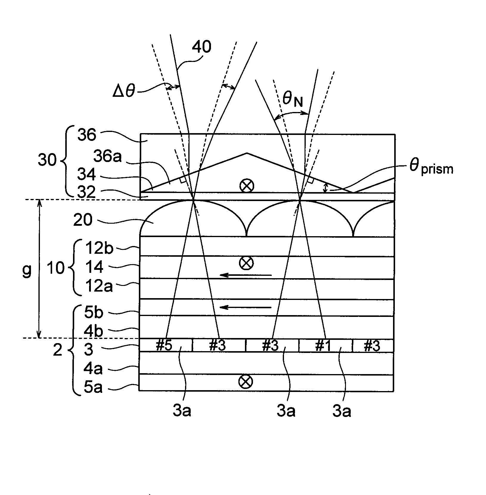
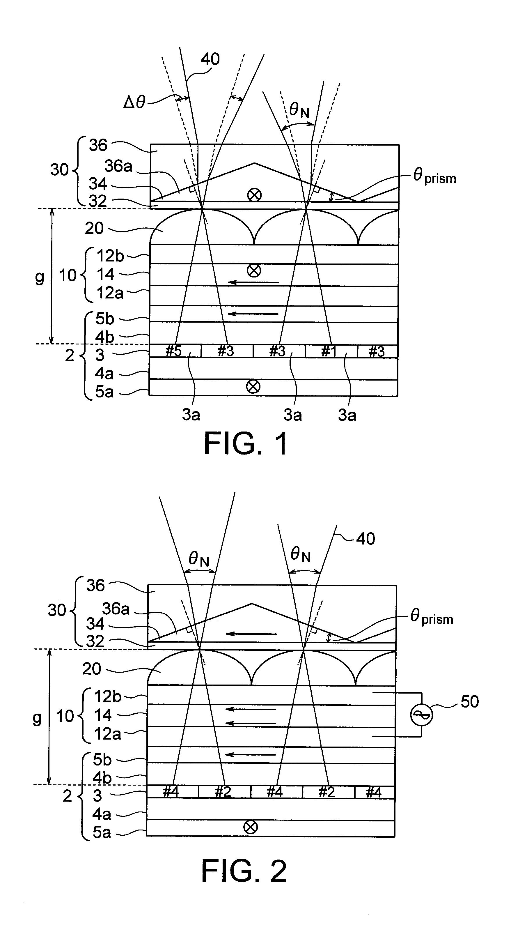
[0052]A stereoscopic image display apparatus according to a first embodiment of the present invention will now be described with reference to FIGS. 1 and 2.

[0053]FIG. 1 shows a horizontal section of the stereoscopic image display apparatus according to the present embodiment. The stereoscopic image display apparatus according to the present embodiment includes a plane display device 2, a variable polarization cell 10, a lens array 20 serving as an optical plate, and a double refraction prism array 30.

[0054]The plane display device 2 is, for example, a liquid crystal display device. The plane display device 2 includes a display part 3 having pixels 3a arranged in a matrix form, one pair of transparent substrates 4a and 4b provided so as to have the display part therebetween, and vertical polarizers (sheet polarizers) 5a and 5b respectively provided on surfaces of the transparent substrates 4a and 4b opposite to the display part 3. The vertical polarizer 5a is different in light polar...

second embodiment

[0104]A stereoscopic image display apparatus according to a second embodiment of the present invention will now be described.

[0105]If the variable polarization cell 10 is placed between the lens array 20 and the plane display device 2 as shown in FIGS. 1 and 2, then the gap g between the lens array 20 and pixels of the plane display device 2 cannot be made smaller than the thickness of the variable polarization cell 10. According to the expression (6), the gap g between the lens array 20 and pixels of the plane display device 2 is inversely proportional to the viewing angle 2θ, and proportional to the subpixel pitch sp and the number N of parallaxes. For making the gap g small, therefore, it is necessary to make the viewing angle 2θ wide, make the subpixel pitch small, or make the number N of parallaxes small. In these cases, however, it is difficult to configure the stereoscopic image display apparatus. Therefore, the stereoscopic image display apparatus according to the present ha...

third embodiment

[0112]A stereoscopic image display apparatus according to a third embodiment of the present invention will now be described with reference to FIG. 14.

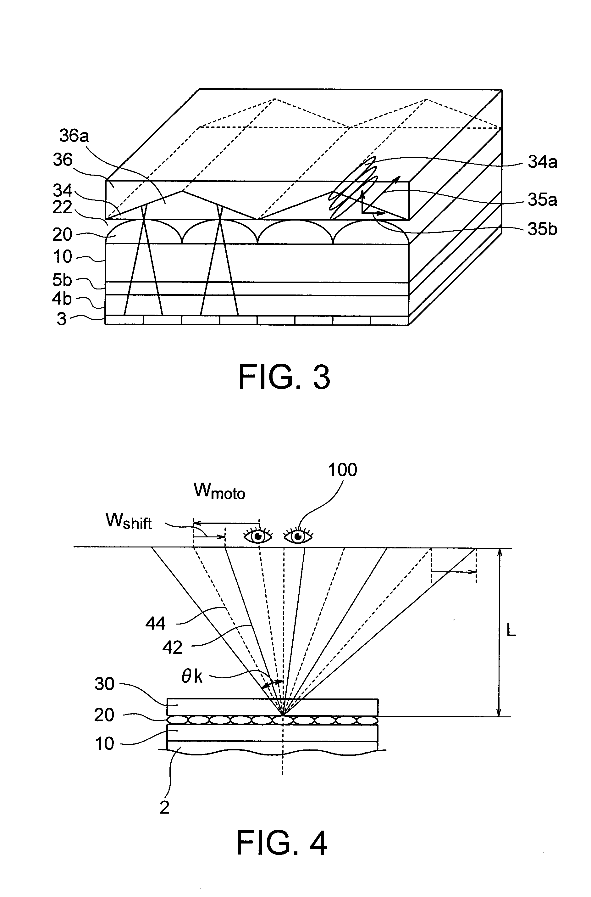
[0113]FIG. 14 shows a horizontal section of a stereoscopic image display apparatus according to the present embodiment. The stereoscopic image display apparatus according to the present embodiment has a configuration which does not use liquid crystal but uses solidified UV setting liquid crystal monomer 35 as the double refraction substance 34 in the double refraction prism array 30 in the stereoscopic image display apparatus according to the first embodiment shown in FIG. 1. As a result, it becomes possible to eliminate the lower substrate 32 in the double refraction prism array 30, and the double refraction prism array 30 can be made to further approach the lens array 20.


PUM


Abstract

A stereoscopic image display apparatus includes: a plane display device; a lens array provided in front of the display surface to distribute light rays from pixels of the display device to predetermined angles, and having a plurality of lenses arranged in a first direction; a variable polarizer provided between the plane display device and the lens array to polarize light rays from the pixels; and a double refraction prism array provided on an opposite side of the lens array from the display device, and including a plurality of double refraction prisms. Each of the double refraction prisms has a ridge in a second direction perpendicular to the first direction and arranged in the first direction with a pitch which is substantially twice a lens pitch in the lens array, and has double refraction in which a refractive index in a ridge direction is different from a refractive index in a direction perpendicular to the ridge direction.

Description

CROSS-REFERENCE TO RELATED APPLICATION[0001]This application is based upon and claims the benefit of priority from prior Japanese Patent Application No. 2008-81288 filed on Mar. 26, 2007 in Japan, the entire contents of which are incorporated herein by reference.BACKGROUND OF THE INVENTION[0002]1. Field of the Invention[0003]The present invention relates to a stereoscopic image display apparatus.[0004]2. Related Art[0005]The integral photography method (hereafter referred to as IP method) of displaying a large number of parallax images or the light ray reproduction method of recording a stereoscopic image by using any method and reproducing it as a stereoscopic image is known. It is supposed that an object is viewed with left and right eyes. When a point located at a short distance is viewed, an angle formed by the point and the left and right eyes is denoted by α. When a point located at a long distance is viewed, an angle formed by the point and the left and right eyes is denoted ...

Claims


Application Information

Patent Timeline
Patent Type & Authority Applications(United States)
IPC IPC(8): H04N13/04G02B30/25G02B30/27
CPCG02B27/26G02B27/2214G02B30/25G02B30/27
Inventor TAKAGI, AYAKOKASHIWAGI, MASAKOSAISHU, TATSUOHIRAYAMA, YUZO
Owner KK TOSHIBA
Why Eureka
Try Eureka