
Filter switching device, photographing lens, camera, and image pickup system

a filter switching and image technology, applied in the field of filter switching devices, can solve the problems of color reproducibility (faithfulness) of obtained image data, the filter used is not disclosed, and the workability of the image pickup operation is reduced, so as to simplify the image pickup procedure and facilitate error-free image data processing. , the effect of improving workability

Inactive Publication Date: 2009-10-01
OLYMPUS CORP
View PDF10 Cites 54 Cited by
  • Summary
  • Abstract
  • Description
  • Claims
  • Application Information

AI Technical Summary

Benefits of technology

The invention relates to a technique for processing image data obtained from a camera. The technique allows for error-free processing without the need for a photographer to record information about the filters used during image pickup. The invention also simplifies the image pickup procedure and improves workability during image pickup operation. Additionally, the invention provides a method for associating the filter used during image pickup with the image data obtained from the camera, allowing for easier color reproduction and improved image quality. The invention can be applied to a filter switching device, a photographing lens, and a lens-replaceable camera.

Problems solved by technology

The technique described above does not disclose a method of associating the filter used during photographing with the image (image data) obtained as a result of the image pickup.
Furthermore, when image data are processed subsequently, information relating to the spectral transmittances to be applied must be specified (input) in accordance with the respective image data, which is inefficient.
Also, when an error occurs during recording of the used filter or input of the spectral transmittance information, the color reproducibility (faithfulness) of the obtained image data decreases greatly.

Method used


Image

  • Filter switching device, photographing lens, camera, and image pickup system
  • Filter switching device, photographing lens, camera, and image pickup system
  • Filter switching device, photographing lens, camera, and image pickup system

Examples


Embodiment Construction

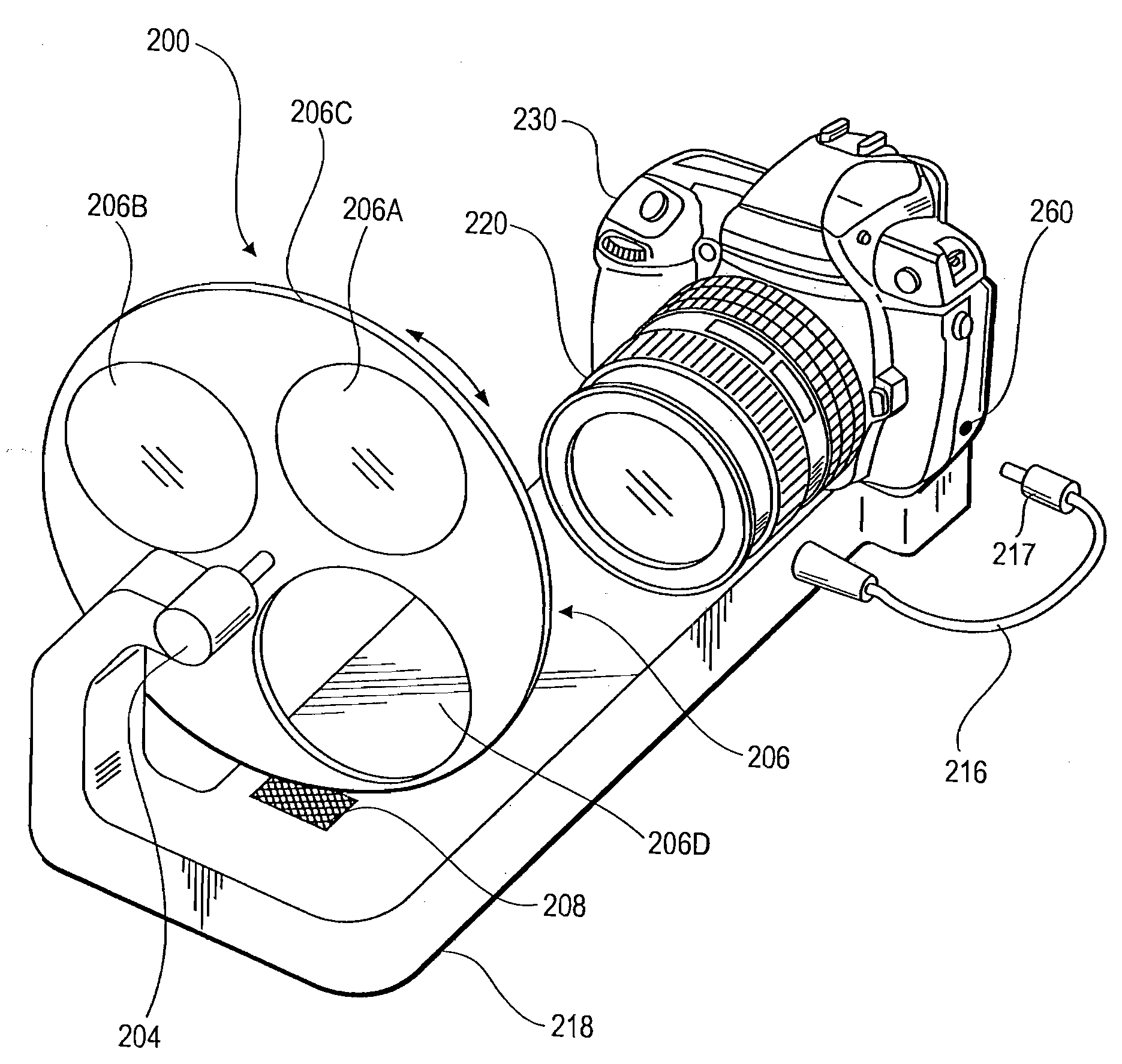
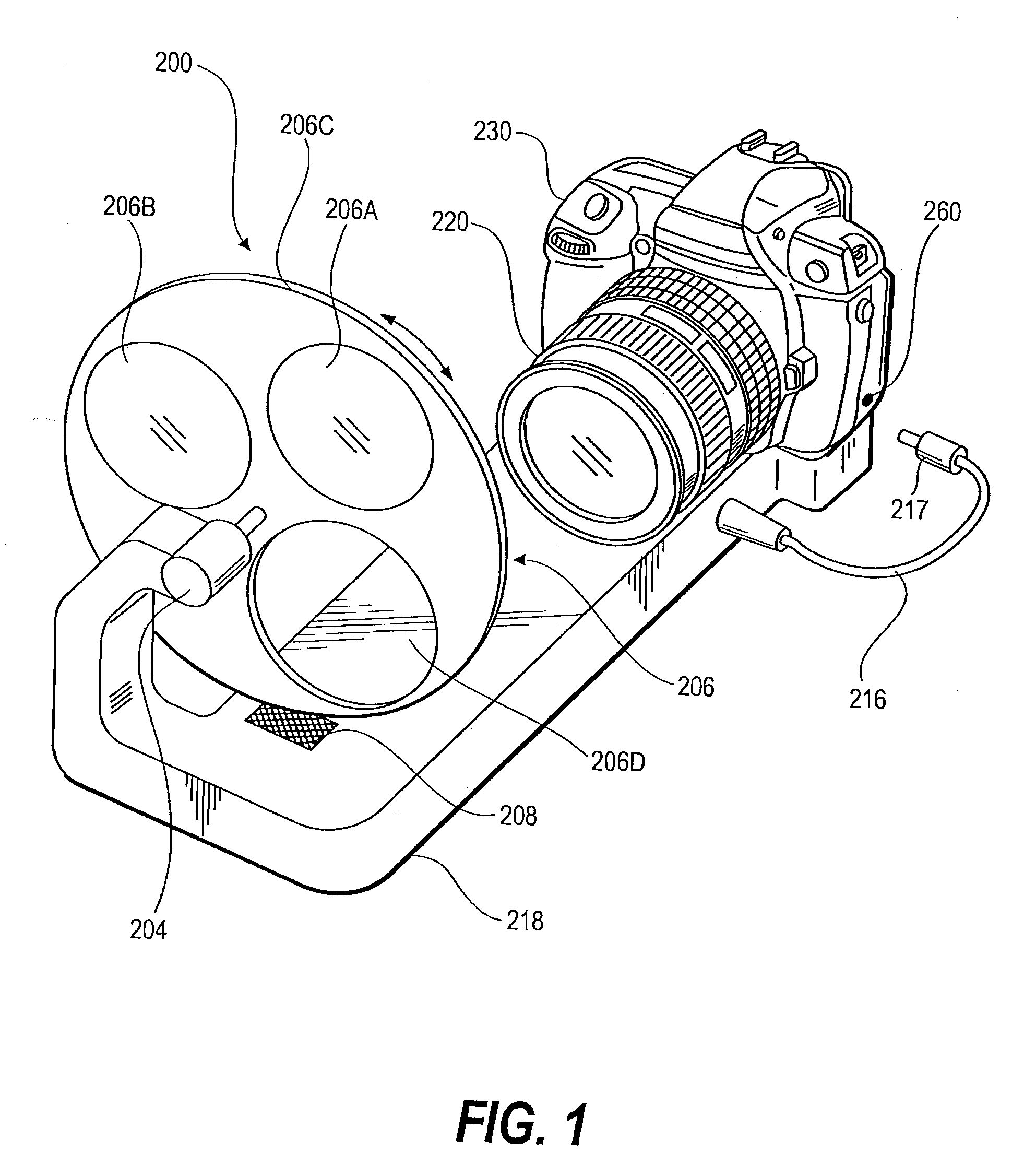
[0057]FIG. 1 is a perspective view showing an example in which a filter switching device 200 according to an embodiment of this invention is used together with a camera 230 and a photographing lens 220. In the example shown in FIG. 1, the camera 230 is a single lens reflex type electronic camera in which an imaging device incorporated into the interior thereof is a single plate type device having red (R), green (G) and blue (B) on-chip color filters or a multi-plate type device employing a spectral optical system such as a dichroic prism. The photographing lens 220 can be attached to and detached from the camera 230 freely, and is therefore replaceable. It should be noted, however, that this invention is not limited to the example described above, and the number of colors of the image signals that can be output from the imaging device may be set at four or more. Moreover, the camera 230 is not limited to a single lens reflex type, and the lens may be replaceable or fixed.

[0058]The f...


PUM

PropertyMeasurementUnit
wavelength rangeaaaaaaaaaa

Abstract

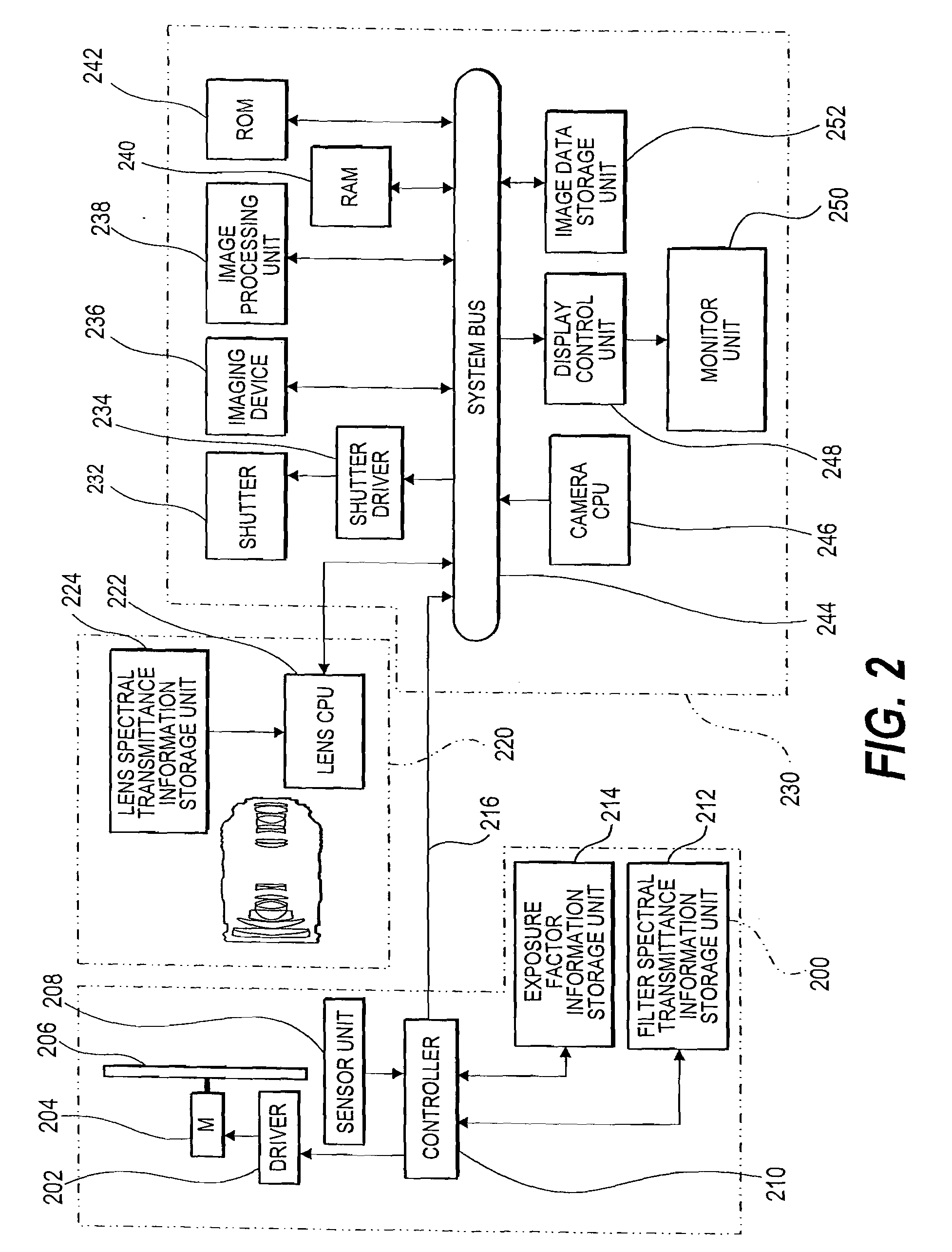
A filter switching device includes: an optical filter unit that is disposed on an optical path of an object light that passes through an image pickup lens of a camera, and can be switched to any one of a plurality of spectral transmission characteristics; a spectral transmission characteristic switching unit that switches a spectral transmission characteristic of the optical filter unit to one of the plurality of spectral transmission characteristics; a filter spectral transmission characteristic information storage unit that stores filter spectral transmission characteristic information, which is information relating to each of the plurality of spectral transmission characteristics; and a filter spectral transmission characteristic information output unit that outputs filter spectral transmission characteristic information corresponding to the spectral transmission characteristic of the optical filter unit to the camera when the spectral transmission characteristic of the optical filter unit is switched.

Description

FIELD OF THE INVENTION[0001]This invention relates to a filter switching device, a photographing lens, a camera, and an image pickup system that are suitable for use in generating an image having a larger number of bands than three.DESCRIPTION OF THE RELATED ART[0002]A technique for performing image pickup using a band pass filter having a larger number of bands than three has been developed as a method of reproducing colors more faithfully and naturally through multi-primary color image expression that is not constrained to the conventional three primary colors. In this specification, a larger number of bands than three will be referred to as “multiband”, an image constituted by a larger number of primary colors than three will be referred to as a “multi-primary color image”, an image constituted by a larger number of spectra than three will be referred to as a “multi-spectrum image”, and so on.[0003]JP2002-296114A discloses a technique for obtaining a multi-spectrum image. This te...

Claims


Application Information

Patent Timeline
Patent Type & Authority Applications(United States)
IPC IPC(8): H04N5/225G02B5/28G02B5/22G02F1/29H04N23/12H04N23/75
CPCG02B5/22H04N5/232H04N5/2254G02B5/28H04N23/60H04N23/55
Inventor HORIE, TAKUJI
Owner OLYMPUS CORP
Learn More