
Liquid crystal display device

Inactive Publication Date: 2009-10-01
PANASONIC LIQUID CRYSTAL DISPLAY CO LTD +1
View PDF1 Cites 4 Cited by
  • Summary
  • Abstract
  • Description
  • Claims
  • Application Information

AI Technical Summary

Benefits of technology

[0008]To display a normal liquid crystal image on a liquid crystal display device having the above-described device, backlight light with high directivity is scattered due to scattering characteristic of the liquid crystal shutter before being input to the liquid crystal cell closer to a viewer, which results in less viewing angle dependency with respect to brightness. Meanwhile, to display a specific image with high visibility when viewed from the front direction but poor visibility when viewed from a diagonal direction, a voltage is applied to the liquid crystal shutter provided behind the liquid crystal display panel, upon which the scattering characteristic of the liquid crystal shutter is eliminated and the liquid crystal shutter becomes transparent in appearance. With the liquid crystal shutter being transparent, light with strong directivity from a light source is not scattered before being input to the liquid crystal panel, and resultantly, a liquid crystal image with strong directivity is displayed. When strong forward directivity from the backlight is set, a third party looking at the liquid crystal display image from a direction other than the front direction will see only a hardly visible dark image.
[0009]To display an image on a liquid crystal display panel, a scanning signal, an image signal, power, and the like need to be constantly supplied to the liquid crystal display panel via a liquid crystal display panel flexible cable connected to a terminal of the liquid crystal display panel. Further, to display a normal image in the liquid crystal display device, light from a CCFL is scattered by the liquid crystal shutter, utilizing characteristic thereof to scatter passing light, to thereby enhance visibility when viewed from a diagonal direction. Meanwhile, to display an image which is desired to be seen only from the front direction on the liquid crystal display panel, electricity is applied to the liquid crystal shutter, and the liquid crystal shutter becomes transparent in appearance. In the above, an electric signal needs to be supplied also to the liquid crystal shutter side.
[0010]Therefore, in a liquid crystal display device capable of displaying a normal image and a specific image on a liquid crystal display panel, each of the two liquid crystal panels needs a power supply and signal supply, and the like. This results in complicated wiring and increased manufacturing cost.
[0012]In one embodiment of the present invention, as the flexible cable from the liquid crystal display panel and that from the liquid crystal shutter are connected to the same printed circuit board, it is possible to reduce the material cost of a printed circuit board and a connecter for use in connection from the printed circuit board to an external circuit. Further, as the number of steps of assembling the liquid crystal display device can be reduced, the manufacturing cost of the liquid crystal display device can be reduced.
[0013]In another embodiment of the present invention, a smaller interval is defined between the flexible cable from the liquid crystal display panel and that from the liquid crystal shutter, the two flexible cables can be readily connected to the same printed circuit board and also the size of the printed circuit board can be made smaller. Therefore, reduction of the material cost of and the number of steps of assembling the liquid crystal display device can be reduced, which can reduce the cost of the liquid crystal display device.

Problems solved by technology

This results in complicated wiring and increased manufacturing cost.

Method used


Image

  • Liquid crystal display device
  • Liquid crystal display device
  • Liquid crystal display device

Examples


Embodiment Construction

[0023]An embodiment of the present invention will be described in the following.

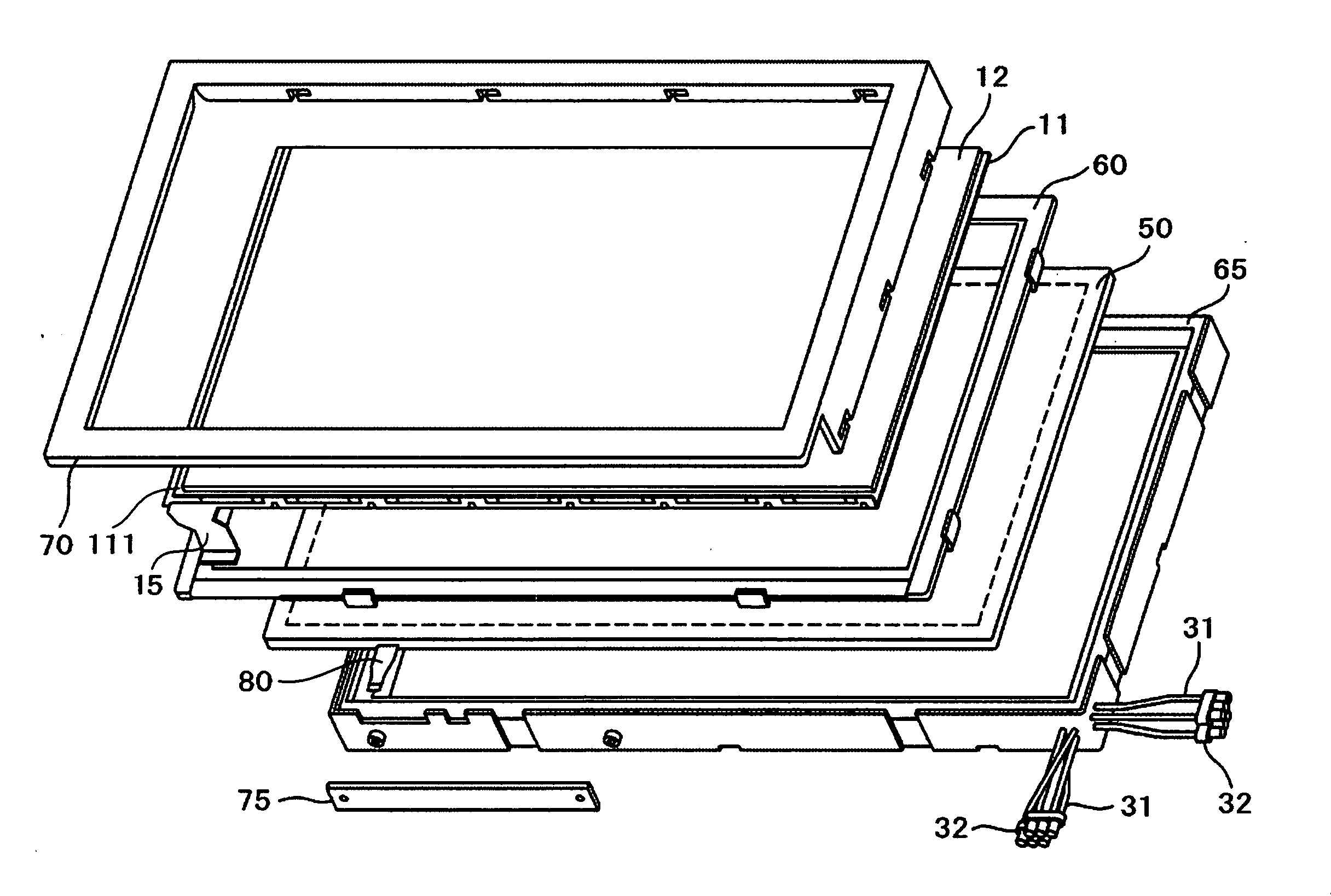
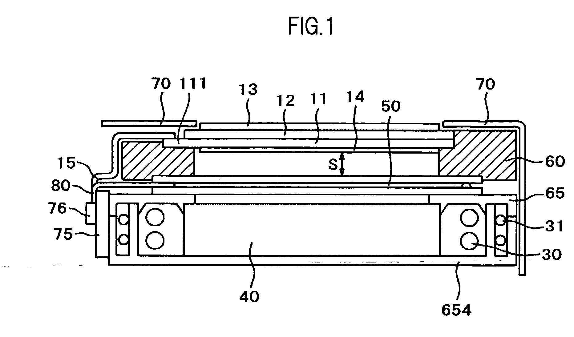
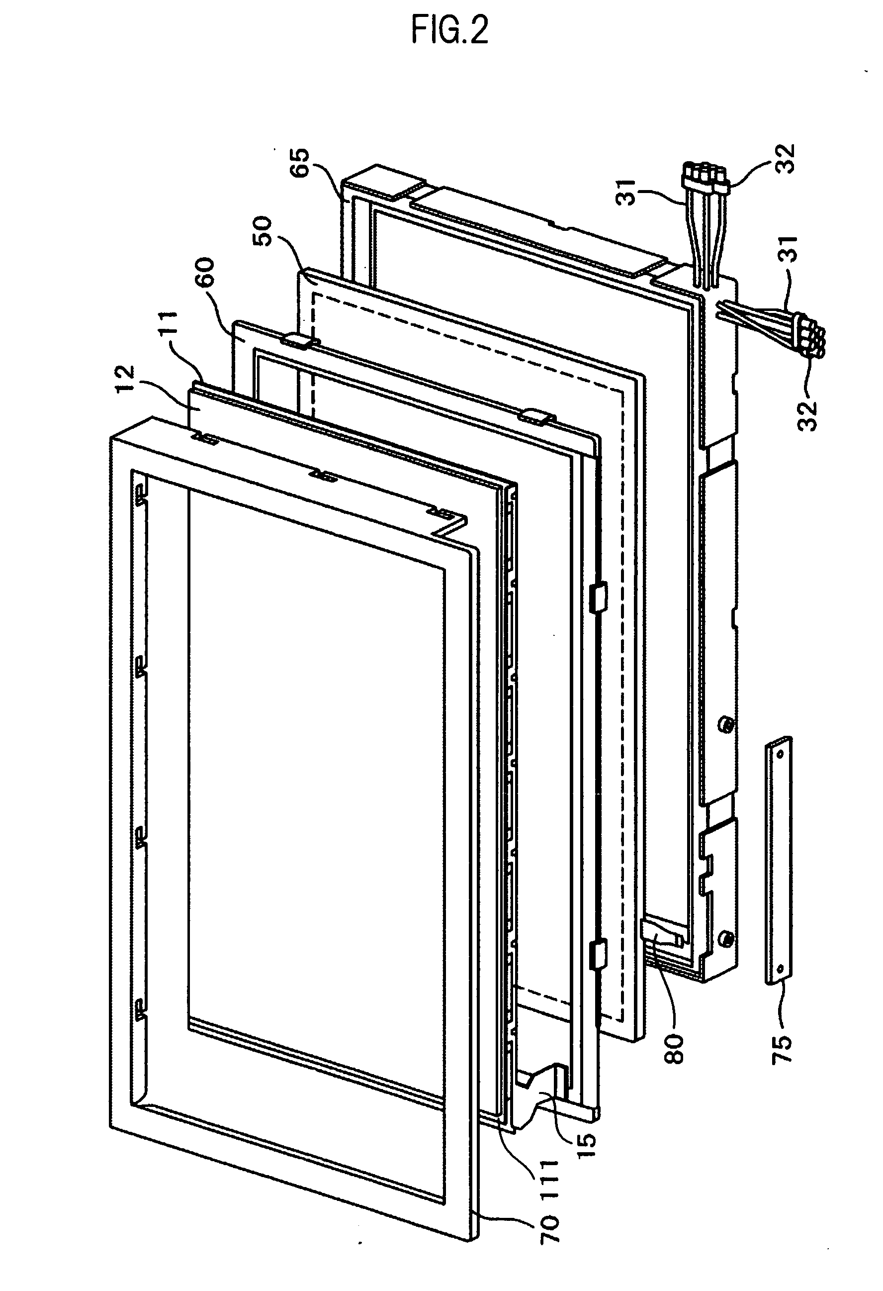
[0024]FIG. 1 is a schematic cross sectional view of a liquid crystal display device according to an embodiment of the present invention. In FIG. 1, a liquid crystal display panel is mounted on an upper mold 60. The liquid crystal display panel comprises a TFT substrate 11 where a pixel electrode, a TFT, and the like are formed, and an opposed substrate 12 where a color filter and the like is formed, with liquid crystal enclosed between the TFT substrate 11 and the opposed substrate 12. A lower polarizer 14 is attached on the lower surface of the TFT substrate 11, and an upper polarizer 13 is attached on the upper surface of the opposed substrate 12.

[0025]The TFT substrate 11 is slightly larger in size than the opposed substrate 12. A terminal 111 via which to supply power, a signal, and so forth to the liquid crystal panel is formed where the TFT substrate 11 remains alone. And the flexible cable 15 for ...


PUM


Abstract

A liquid crystal shutter (50) is provided behind a liquid crystal display panel, and a light source accommodated in a lower mold (65) is provided behind the liquid crystal shutter (50). As a liquid crystal display panel flexible cable (15) and a liquid crystal shutter flexible cable (80) are placed close to each other, and connected to the same printed circuit board (75), the number of printed circuit boards (75) is able to be saved to one, as well as the number of connecters (76) for connecting the printed circuit board (75) to the outside.

Description

CROSS-REFERENCE TO RELATED APPLICATION[0001]The present application claims priority from Japanese Application JP2008-078132 filed on Mar. 25, 2008, the content of which is hereby incorporated by reference into this application.BACKGROUND OF THE INVENTION[0002]1. Field of the Invention[0003]The present invention relates to a display device, and more particularly to a liquid crystal display device having a plurality of liquid crystal cells stacked on in a direction perpendicular to the display surface.[0004]2. Description of the Related Art[0005]There is an increasing demand for a liquid crystal display device for use with a computer display, a portable phone terminal, a television, and the like. When a liquid crystal display device outputs a normal liquid crystal display image, an image with high visibility irrespective of a direction from which to see is required. Meanwhile, when a specific image for, e.g., password input or the like, is shown on a liquid crystal display device used...

Claims


Application Information

Patent Timeline
IPC IPC(8): G02F1/1345
CPCG02F1/13476G02F1/13452
Inventor YAMATE, HIROSHI
Owner PANASONIC LIQUID CRYSTAL DISPLAY CO LTD
Features
  • Generate Ideas
  • Intellectual Property
  • Life Sciences
  • Materials
  • Tech Scout
  • Unparalleled Data Quality
  • Higher Quality Content
  • 60% Fewer Hallucinations
Learn More