Laser light source device

Inactive Publication Date: 2009-10-01
FUJIFILM CORP
View PDF2 Cites 25 Cited by
  • Summary
  • Abstract
  • Description
  • Claims
  • Application Information

AI Technical Summary

Benefits of technology

[0008]In view of the above-described circumstances, the present invention is directed to providing a laser light source device which reduces co

Problems solved by technology

However, an illumination device employing the laser light source device may suffer from degradation of illumination performance caused by an uneven illumination pattern (hereinafter referred to as “speckle”) due to coherence of the laser light.
Further, in an imaging apparatus employing the laser light source device as the illumination device, the speckle of the laser light may significantly degrade quality of an acquired image.
However, since the speckle phenomenon is caused by the coherence of the laser light, if reduction of the coherence of the laser light is insufficient in the laser light source devices disclo

Method used


Image

  • Laser light source device
  • Laser light source device
  • Laser light source device

Examples


Example

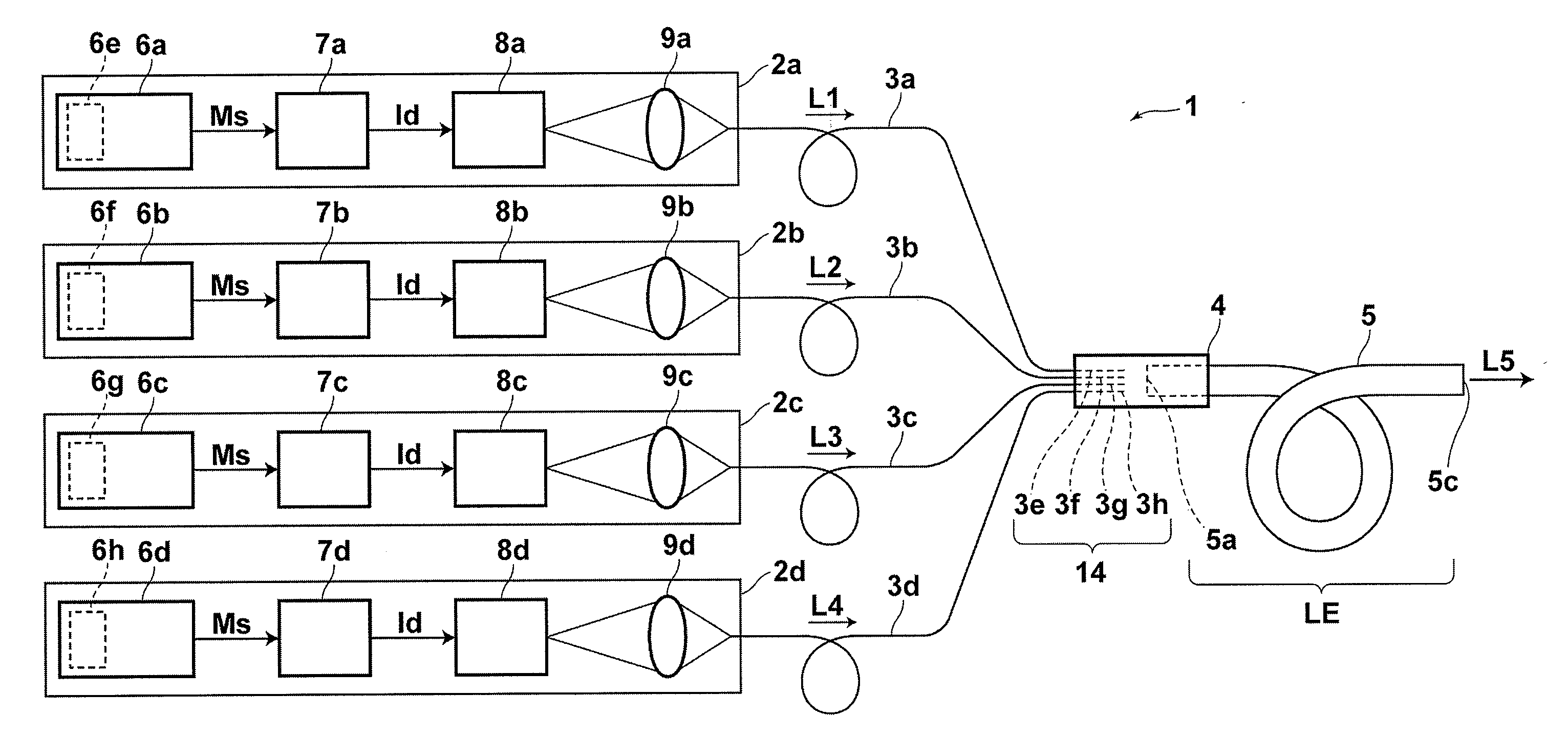
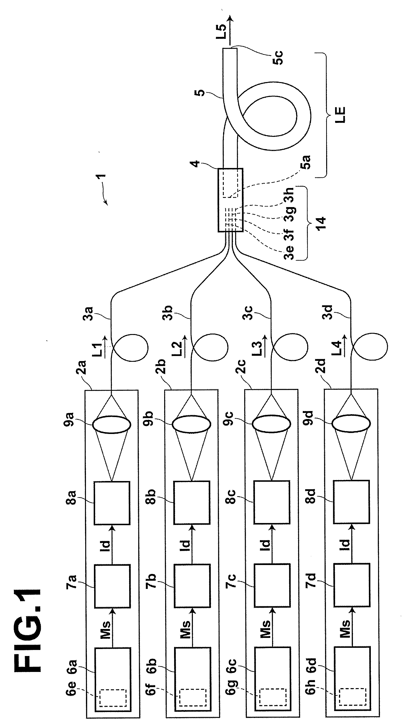
[0025]Hereinafter, a laser light source device of the present invention will be described with reference to the drawings. FIG. 1 illustrates the schematic configuration of a laser light source device 1 of the invention. As shown in FIG. 1, the laser light source device 1 includes four laser modules 2a to 2d. Optical fibers 3a to 3d of the laser modules 2a to 2d are bundled at a position in the vicinity of output ends 3e to 3h of the optical fibers 3a to 3d, and are optically connected to an input end 5a of a multimode optical fiber 5 via an optical connector 4. Although the laser light source device 1 described in this embodiment includes the four laser modules, as one example, this is not intended to limit the invention, and the laser light source device 1 may include two or more laser modules.

[0026]Next, the laser modules 2a to 2d are described. The laser modules 2a to 2d respectively include: signal generators 6a to 6d to generate modulation signals Ms; laser drivers 7a to 7d to ...


PUM


Abstract

A laser light source device is disclosed, which reduces the coherence of the laser light and inexpensively achieves a visually recognizable level of speckle reduction without use of a mechanical driving means. The laser light source device includes: laser modules, each including a laser light source, an intensity modulation unit to apply intensity modulation to laser light emitted from the laser light source, and a first waveguide to receive the intensity-modulated laser light from the laser light source and output the laser light from an output end thereof; and a second waveguide including an input end optically connected to a light outputting area of the first waveguides to receive the laser light outputted from the first waveguides, the first waveguides being closely bundled in the vicinity of output ends thereof, wherein a core of the second waveguide at the input end is larger than the light outputting area.

Description

BACKGROUND OF THE INVENTION[0001]1. Field of the Invention[0002]The present invention relates to a laser light source device, and in particular to a laser light source device having reduced speckle of laser light emitted therefrom.[0003]2. Description of the Related Art[0004]Laser light source devices have conventionally been used as an illumination device for use with an endoscope or interferometer. Such an illumination device is required to provide uniform illumination light. However, an illumination device employing the laser light source device may suffer from degradation of illumination performance caused by an uneven illumination pattern (hereinafter referred to as “speckle”) due to coherence of the laser light. Further, in an imaging apparatus employing the laser light source device as the illumination device, the speckle of the laser light may significantly degrade quality of an acquired image.[0005]Japanese Unexamined Patent Publication No. 2003-156698 proposes a laser ligh...

Claims


Application Information

Patent Timeline
IPC IPC(8): H01S3/10H01S5/026
CPCH01S3/06737H01S5/0652H01S3/2383H01S3/06745H01S3/005
Inventor SHIMOTSU, SHINICHI
Owner FUJIFILM CORP
Why Eureka
Try Eureka