Audio Power Amplifier with Feedback-Shifting Technology

a technology of audio power amplifier and feedback, which is applied in the direction of low frequency amplifier, transducer casing/cabinet/support, electrical transducer, etc., can solve the problems of listening fatigue, non-feedback audio power amplifier has two big problems to be solved, and the soundstage is confined, etc., to achieve low cost and high performance

Inactive Publication Date: 2009-10-01
WANG ZHENWU
View PDF2 Cites 25 Cited by
  • Summary
  • Abstract
  • Description
  • Claims
  • Application Information

AI Technical Summary

Benefits of technology

[0009]The present invention is accomplished upon the previously mentioned circumstances. An object of the invention is to provid...

Problems solved by technology

However, since the speaker system which the amplifier drives is not a simple resistive load, the moving voice coil also generates back Electro Motive Force (EMF) and feeds it back to the input of the amplifier through the global feedback loop.
This back EMF signal inevitably interferes with the incoming input signal, causing unwanted effect in the reproduced sound like missing the subtle detail of music, constraining the soundstage and causing listening fatigue as claimed by many audiophiles.
However, non-feedback audio power amplifier has two big problems need to be solved: non-linear distortions, especially the crossover distortion generated by the output stage, and the high output impedance.
The crossover distortion generates numerous odd number high order harmonics which will cause listening fatigue and greatly degrade the perceived sound quality.
Such a solution inevitably increases the cost and power consumption, making the technique only suitable in the very limited high-end market.
However, this idea also has a problem.
While an amplifier employing such a tech...

Method used


Image

  • Audio Power Amplifier with Feedback-Shifting Technology
  • Audio Power Amplifier with Feedback-Shifting Technology
  • Audio Power Amplifier with Feedback-Shifting Technology

Examples


Embodiment Construction

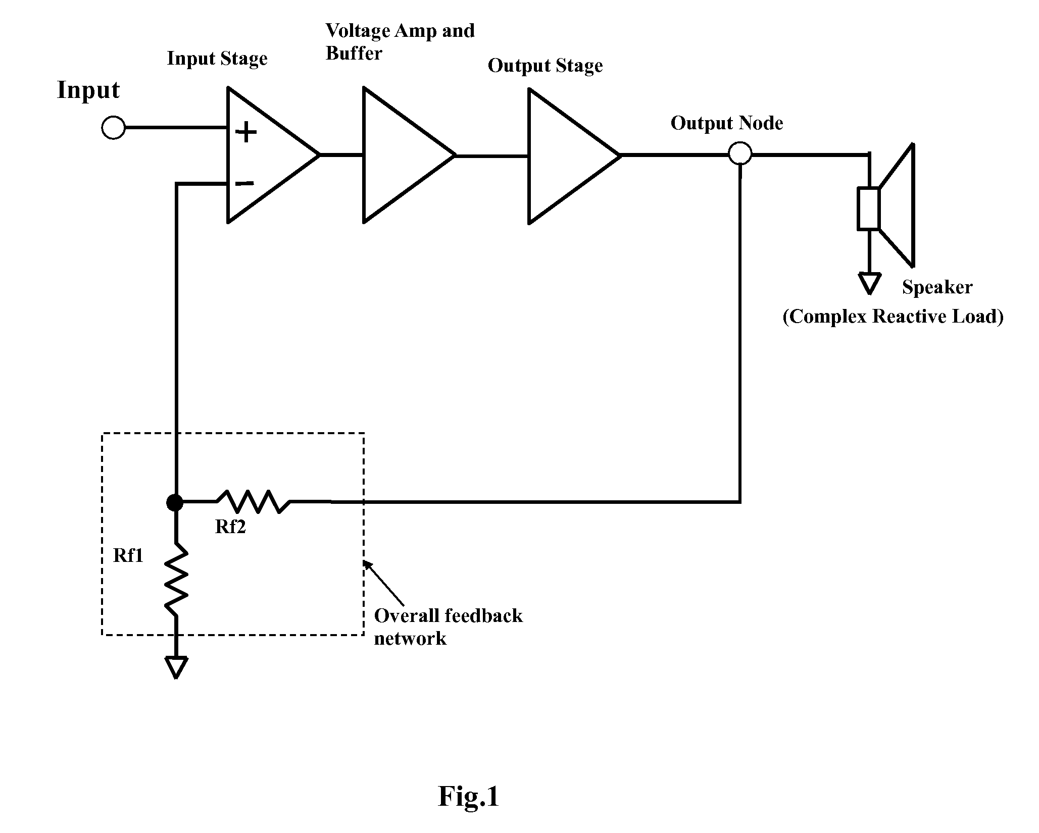
[0024]FIG. 3 shows an audio power amplifier block diagram according to one embodiment of the invention. The amplifier comprises an input node 1, an input stage 2, a voltage amp and buffer 4, a real output stage 6, a dummy output stage 7, a speaker load 10 which is connected to the output node 8 of the real output stage 6, a dummy resistive load 11 which is connected to the output node 9 of the dummy output stage 7, a Feedback-Shifting network 12, a global feedback network 14 which consists of resister Rf1 and Rf2 and is connected between the center point 13 of the feedback shifting network 12 and the inverting input node 15 of the input stage 2.

[0025]The input signal is amplified by the input stage 2 and passed to the voltage amp and buffer 4 through its output node 3. The amplified signal is further amplified and passed to the input of the real output stage 6 and the input of the dummy output stage 7 through the output node 5 of the voltage amp and buffer 4. The two output stages a...


PUM


Abstract

A solid stage audio power amplifier comprises of two output stages with one generating the real output signal that drives the real loud speaker load and the other mimicking the real output stage and generating a dummy output signal that drives a dummy resistor load. A frequency dependent feedback selection network, denoted as Feedback-Shifting network hereafter, is implemented between the two outputs and the input of the amplifier to fulfill a unique global feedback loop. In a particular embodiment, the Feedback-Shifting network can be constructed so that it receives more feedback information from the real output node than from the dummy output node at low frequencies, but less feedback information from the real output node than from the dummy output node at mid to high frequency bands. Such a power amplifier performs as a traditional solid state feedback amplifier at low frequencies by generating a clear and tight bass, but it sounds similar to an open loop tube amplifier at higher frequencies by reproducing natural mid-band and treble with less listening fatigue.

Description

CROSS REFERENCE OF RELATED APPLICATION[0001]This is a regular application of a provisional application having an application number of 61 / 210,227 and a filing date of Mar. 16, 2009.BACKGROUND OF THE INVENTION[0002]The invention relates to solid state audio power amplifiers for driving loud speaker systems to carry out high quality sound reproduction.[0003]Solid state audio power amplifiers usually adopt overall negative feedback loops in order to reduce distortions and improve other key characteristics as shown in FIG. 1. However, since the speaker system which the amplifier drives is not a simple resistive load, the moving voice coil also generates back Electro Motive Force (EMF) and feeds it back to the input of the amplifier through the global feedback loop. This back EMF signal inevitably interferes with the incoming input signal, causing unwanted effect in the reproduced sound like missing the subtle detail of music, constraining the soundstage and causing listening fatigue as ...

Claims


Application Information

Patent Timeline
IPC IPC(8): H03F99/00
CPCH03F1/34H03F2203/45702H03F3/3074H03F3/45085H03F2200/03H03F2200/129H03F2200/144H03F2200/408H03F2200/453H03F2200/456H03F2203/30051H03F2203/30057H03F2203/30078H03F2203/30111H03F2203/45392H03F2203/45604H03F2203/45674H03F3/183
Inventor WANG, ZHENWU
Owner WANG ZHENWU
Why Eureka
Try Eureka