Method for producing porous film

a technology of porous film and film layer, which is applied in the direction of liquid surface applicators, special surfaces, pretreated surfaces, etc., can solve the problem of difficult formation of honeycomb films

Inactive Publication Date: 2009-10-01
FUJIFILM CORP
View PDF0 Cites 3 Cited by
  • Summary
  • Abstract
  • Description
  • Claims
  • Application Information

AI Technical Summary

Benefits of technology

[0009]It is preferred that the second liquid has interfacial tension against water in a range from 5 mN / m to 20 mN / m. In the droplets forming step, it is preferred that humidification is performed to set an atmospheric dew point TD higher than a surface temperature TS of the film.

Problems solved by technology

However, it is difficult to form the honeycomb films with various patterns in which size and distribution of pores are changed due to processes for forming the honeycomb structure.

Method used


Image

  • Method for producing porous film
  • Method for producing porous film
  • Method for producing porous film

Examples


Embodiment Construction

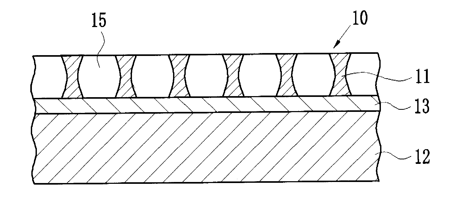
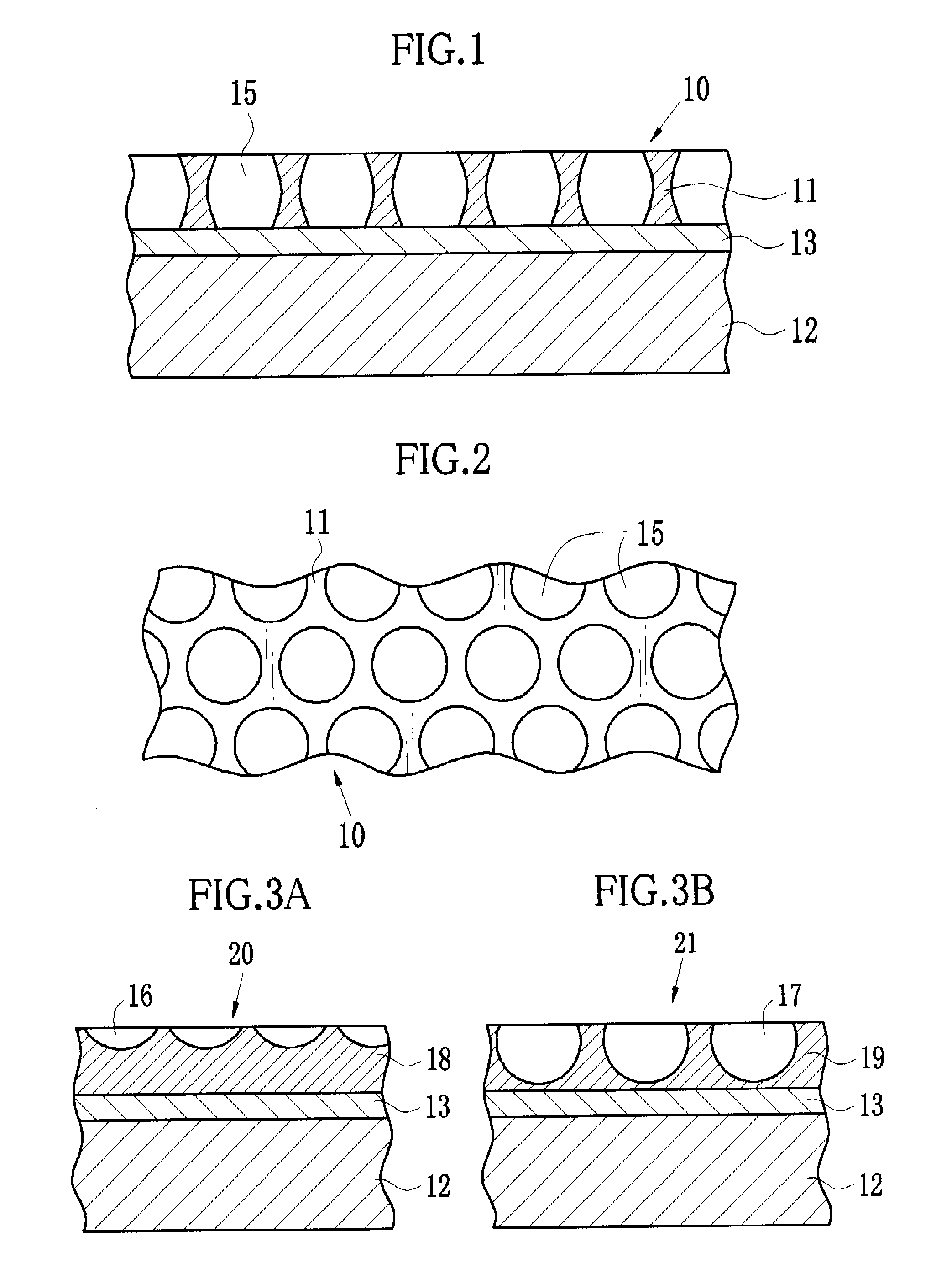
[0020]As shown in FIG. 1, a porous film 10 of the present invention includes a porous layer 11 formed with a plurality of pores 15, a support 12 for supporting the porous layer 11, and a middle layer 13 sandwiched between the porous layer 11 and the support 12. In this embodiment, the pores 15 are independent from each other. Alternatively, the pores may be connected to each other. As shown in FIG. 2, each pore 15 is substantially circular in shape. The porous film 10, as a whole, has a honeycomb structure with densely packed pores 15.

[0021]The pores 15 shown in FIG. 1 are through holes formed in the porous layer 11. Alternatively, shallow pores (hollows) 16 as shown in FIG. 3A or deep pores (hollows) 17 as shown in FIG. 3B may be formed. The pores 15, 16 and 17 are formed on porous layers 11, 18 and 19, respectively, by controlling a droplets growing process, which will be described later. For example, the shallow pores 16 are formed by stopping the growth of droplets at an early s...


PUM


Abstract

A second liquid is applied to a support and dried to form a middle layer. Then, a first liquid is applied to the middle layer. A third liquid is applied to a film of the first liquid using an inkjet type liquid supply unit to form a porous area. The first and third liquids differ in interfacial tension against water. Moist air is supplied to the porous area to cause condensation. In a third chamber, the condensation grows into large droplets, and a solvent is evaporated from the film. Thereafter, the droplets are evaporated from the porous area. Thus, a porous film in which a plurality of pores are arranged is produced. Since the porous area is formed by inkjet printing method, size, shape, and conditions of the porous area is easily changed.

Description

FIELD OF THE INVENTION[0001]The present invention relates to a method for producing a porous film.BACKGROUND OF THE INVENTION[0002]In the fields of optics and electronics, higher integration density, information of higher density, and image information with higher definition are required increasingly. For this reason, films with finer structures are strongly desired in such fields. In the medical field, the films with fine structures (microstructures) are also desired, for example, films that provide scaffolds for the cell culture, and membranes used for hemofiltration.[0003]Examples of the microstructure films include films with honeycomb structures in which a plurality of micropores at a μm level are arranged in a honeycomb-like manner. To produce the honeycomb-structure film, a solution in which a predetermined polymer compound is dissolved in a hydrophobic organic compound is cast, and droplets are formed in a surface of a casting film by condensation. Such droplets are evaporat...

Claims


Application Information

Patent Timeline
Patent Type & Authority Applications(United States)
IPC IPC(8): B05D5/00
CPCB05D1/26B05D1/36B05D5/00B05D3/0254B05D1/42
Inventor ITO, KOJUYAMAZAKI, HIDEKAZU
Owner FUJIFILM CORP
Why Eureka
Try Eureka