Optical film assembly and display device

a technology of optical film and display device, which is applied in the field of optical film assembly and display device, can solve the problems of affecting the performance of the film, the inability to provide the benefit of higher-index materials, and the inability to achieve the benefit of more than 5 wt-%, and achieves the effect of low absorban

Inactive Publication Date: 2009-10-01
3M INNOVATIVE PROPERTIES CO
View PDF86 Cites 13 Cited by
  • Summary
  • Abstract
  • Description
  • Claims
  • Application Information

AI Technical Summary

Benefits of technology

[0015]In each of these embodiments, the microstructured surface preferably comprises the reaction product of a polymerizable resin having a refractive index of at least 1.61. Further, the polymerizable resin preferably has a low absorbance. The microstructured surface typically comprises the reaction product of a polymerizable composition comprising at least one ethylenically unsaturated monomer, optionally at least one ethylenically unsaturated oligomer, and at least 10 wt-% inorganic nanoparticles. Zirconia is a preferred inorganic nanoparticle. The inorganic nanoparticles are preferably fully condensed surface modified inorganic nanoparticles.
[0016]The optical film may comprise a base layer coupled to the microstructured surface. For embodiments wherein the base layer has a high-index axis and the microstructured surface comprises parallel prisms, the prisms are preferably aligned 90 degrees + / −20 degrees to the high-index axis of the base layer.

Problems solved by technology

Films produced from such base layer materials typically have some birefringence as a result of the film manufacturing process.
Although microstructured optical films prepared from such base layers would also have such birefringence, such films are typically not characterized as polarizing films, since such optical films would not be employed as a polarizer in an illuminated (e.g. LCD) display.
Typically, however, the assembly comprises no greater than two microstructured films with prismatic structures proximate each other.
However, the present inventors have discovered that high-index materials alone do not necessarily provide higher gain, particularly in an assembly.
Greater than 5 wt-% is generally disadvantageous in view of the tendency to cause yellow discoloration of the brightness enhancing film.

Method used


Image

  • Optical film assembly and display device
  • Optical film assembly and display device
  • Optical film assembly and display device

Examples


examples

Refractive Index of the Polymerizable Compositions was Determined with a Fischer Scientific Refractometer Co. Model # 6208.

Gain Test Method

[0130]Optical performance of the films was measured using a SpectraScan™ PR-650 SpectraColorimeter with an MS-75 lens, available from Photo Research, Inc, Chatsworth, Calif. The films were placed on top of a diffusely transmissive hollow light box. The diffuse transmission and reflection of the light box can be described as Lambertian. The light box was a six-sided hollow cube measuring approximately 12.5 cm×12.5 cm×11.5 cm (L×W×H) made from diffuse PTFE plates of ˜6 mm thickness. One face of the box is chosen as the sample surface. The hollow light box had a diffuse reflectance of ˜0.83 measured at the sample surface (e.g. ˜83%, averaged over the 400-700 nm wavelength range, measurement method described below). During the gain test, the box is illuminated from within through a ˜1 cm circular hole in the bottom of the box (opposite the sample sur...

example 65

Display Device Example 65

[0162]The assembly of Example 20 (i.e. a crossed sheet pair of substantially non-polarizing microstructured optical films prepared from a polymerizable resin having a refractive index of 1.6525) was compared to a crossed sheet pair of commercially available brightness enhancing films commercially available from 3M Company, St. Paul, Minn. under the trade designation “Vikuiti BEF-II 90 / 50” in a LCD display.

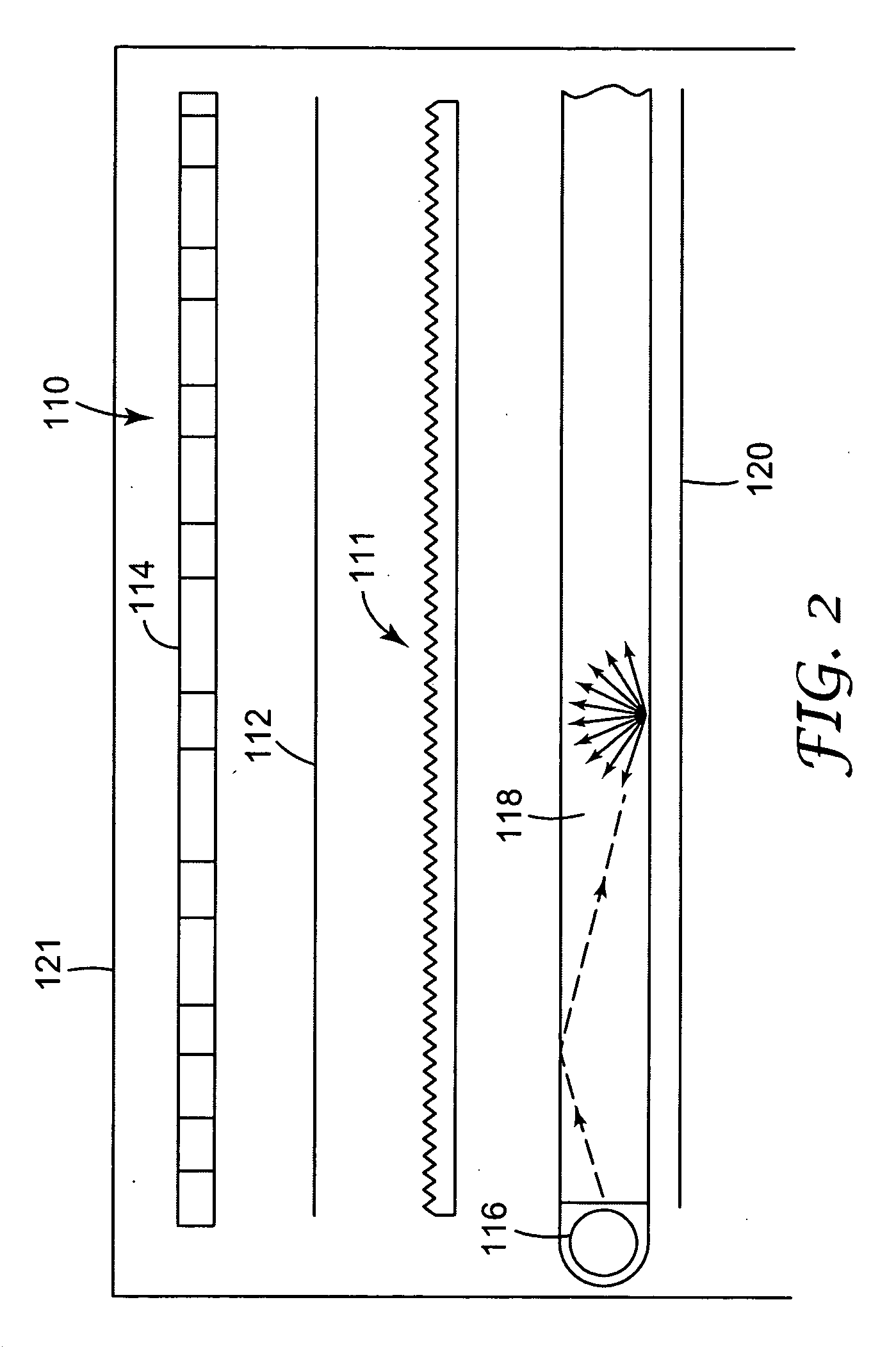
[0163]The LCD module includes a CCFL light source, a wedge-shaped light-guide with a dot extraction pattern, a multi-layer polymeric specular back-reflector behind the light-guide (sold by 3M Company, St. Paul, Minn. under the trade designation ESR [Enhanced Specular Reflector]), a diffusing film in front of the light guide, the assembly of crossed sheet brightness enhancement films in front of the diffusing film, a diffusing cover sheet in front of the BEF II sheets, and lastly a twisted nematic liquid crystal panel having absorbing polarizers on its outer...


PUM

PropertyMeasurementUnit
refractive indexaaaaaaaaaa
thicknessaaaaaaaaaa

Abstract

Microstructured optical films, assemblies of films including at least one microstructured optical film, and (e.g. illuminated) display devices including a single microstructured optical film or assembly.

Description

RELATED APPLICATIONS[0001]This application is a continuation of application Ser. No. 11 / 422,900, filed Jun. 8, 2006, now allowed, which is a continuation-in-part of U.S. patent application Ser. No. 10 / 870,366 filed Jun. 17, 2004; a continuation-in-part of U.S. patent application Ser. No. 10 / 939,184, filed Sep. 10, 2004, issued as U.S. Pat. No. 7,179,513; a continuation-in-part of U.S. patent application Ser. No. 10 / 938,006, filed Sep. 10, 2004, issued as U.S. Pat. No. 7,289,202; a continuation-in-part of U.S. patent application Ser. No. 11 / 078,145 filed Mar. 11, 2005, issued as U.S. Pat. No. 7,282,272; and claims priority to PCT application No. US2005 / 021351, filed Jun. 16, 2005, published as WO2006 / 028543.BACKGROUND[0002]Certain microreplicated optical products, such as described in U.S. Pat. Nos. 5,175,030 and 5,183,597, are commonly referred to as “brightness enhancing films”. Brightness enhancing films are utilized in many electronic products to increase the brightness of a back...

Claims


Application Information

Patent Timeline
Patent Type & Authority Applications(United States)
IPC IPC(8): C09K19/02B32B3/00F21V8/00G02B5/04G02B5/124
CPCG02B5/045Y10T428/24355G02B6/0053G02B6/0065B82Y20/00B82Y30/00C08F2/44C08F222/1006G02B5/02Y10S977/773Y10S977/932Y10S977/84Y10S428/913Y10S977/778Y10S977/939Y10T428/10Y10T428/1041Y10T428/1036Y10T428/24372G02B5/124C08F222/1025C08F222/103C09K2323/00C09K2323/03C09K2323/031Y10T428/31504Y10T428/31855C08G8/10C08J5/18G02B1/04
Inventor JONES, CLINTON L.KOLB, BRANT U.OLSON, DAVID B.GOENNER, EMILY S.HART, SHANDON D.COWHER, JOHN T.
Owner 3M INNOVATIVE PROPERTIES CO
Why Eureka
Try Eureka