Electric power source used with vehicles

a technology of electric power source and vehicle, which is applied in the direction of cell temperature control, electrical equipment, cell components, etc., can solve the problems of shortening the life of the battery, dew formation, and inability to ensure the safety of the battery, so as to reduce the temperature elevation of the battery, simplify the structure, and achieve the effect of reducing the preset temperature of the plate temperature sensor 73

Inactive Publication Date: 2009-10-01
SANYO ELECTRIC CO LTD
View PDF4 Cites 72 Cited by
  • Summary
  • Abstract
  • Description
  • Claims
  • Application Information

AI Technical Summary

Benefits of technology

[0016]Since the electric power source controls a cooled state of the cooling plate by detecting the heat value of the battery in addition to the temperature of the battery block and the temperature of the cooling plate, the dew formation can be prevented, and in addition the battery can be cooled in an ideal state of limiting a temperature elevation of the battery. Since heat is generated inside the battery and thus the temperature is elevated by such heat, there occurs a time delay from such heat generation till the elevation of the battery temperature. Especially, since the temperature sensor detecting the battery temperature detects the temperature produced on the battery surface, there occurs such time delay in detecting the elevation of temperature caused by an interior heat generation. Since the circuit for detecting a heat value detects an amount of heat generated by a charging and discharging current or the like, the heat elevation can be detected before the battery temperature is elevated. In view of this aspect, the temperature elevation of the battery can be reduced to minimum by cooling the battery in a manner that its temperature will not be elevated,

Problems solved by technology

This is because temperature increase of the battery causes electrical characteristics of the battery to decrease as well as shortens a duration of life of the battery and further causes safety to be inhibited.
When the dew is formed and the fan stops its operation, the amount of dew formation does not increase, but disadvantageously a concentrated state lasts longer because the moisture formed into the dew cannot evaporate to be dried.
Further, when the battery temperature is higher than preset temperature in a state of dew formation, the fan is in operation; in such a state, however, since the air is to be forcibly blown in a state of forming the dew, the moisture contained in the air being fed from time to time is formed to dew at a portion that is cooled by low temperature, resulting in an adverse effect that the dew formation gradually increases temporarily.
However, when the battery temperature increases and the temperature of the b

Method used


Image

  • Electric power source used with vehicles
  • Electric power source used with vehicles
  • Electric power source used with vehicles

Examples


Embodiment Construction

)

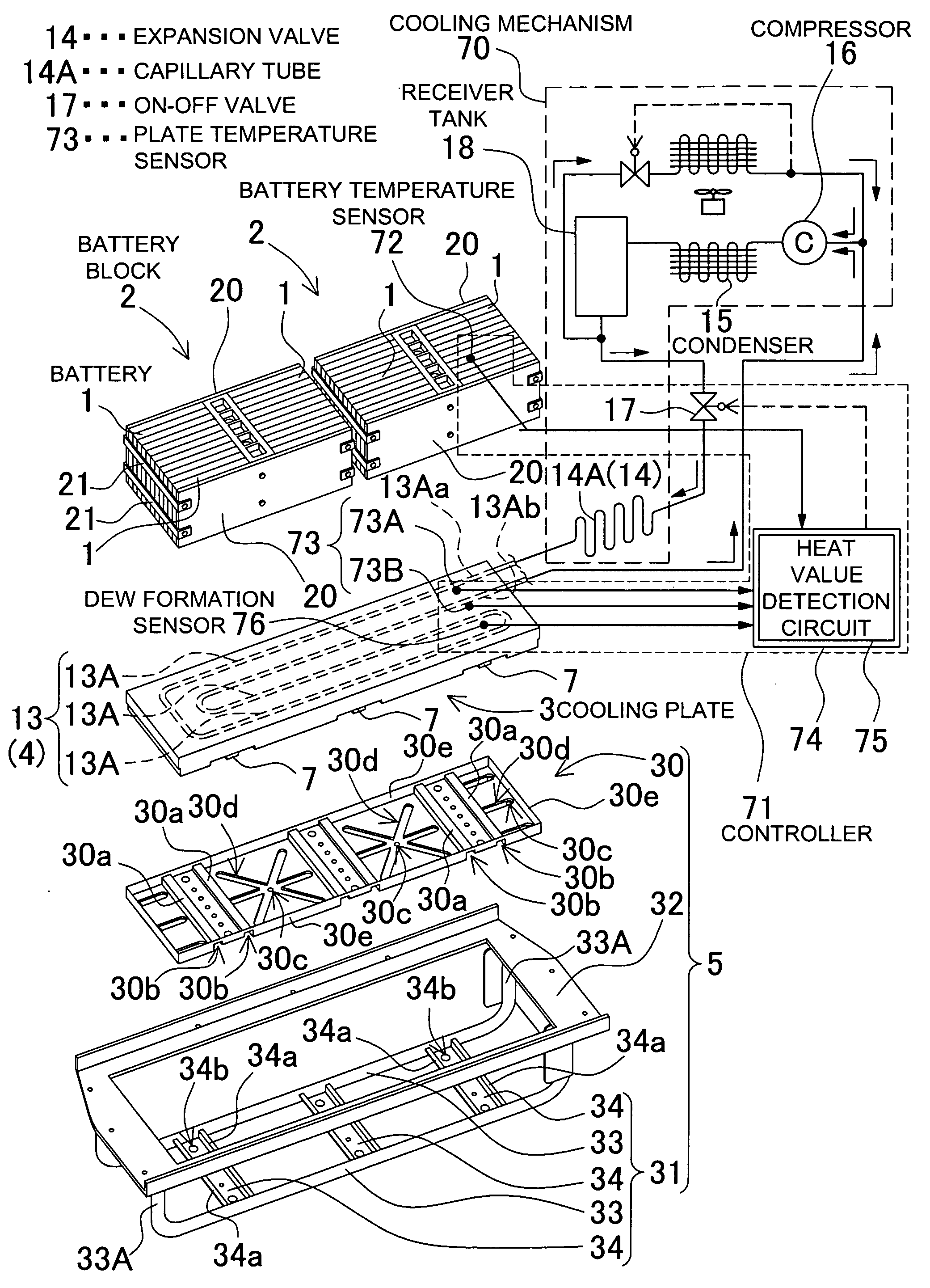
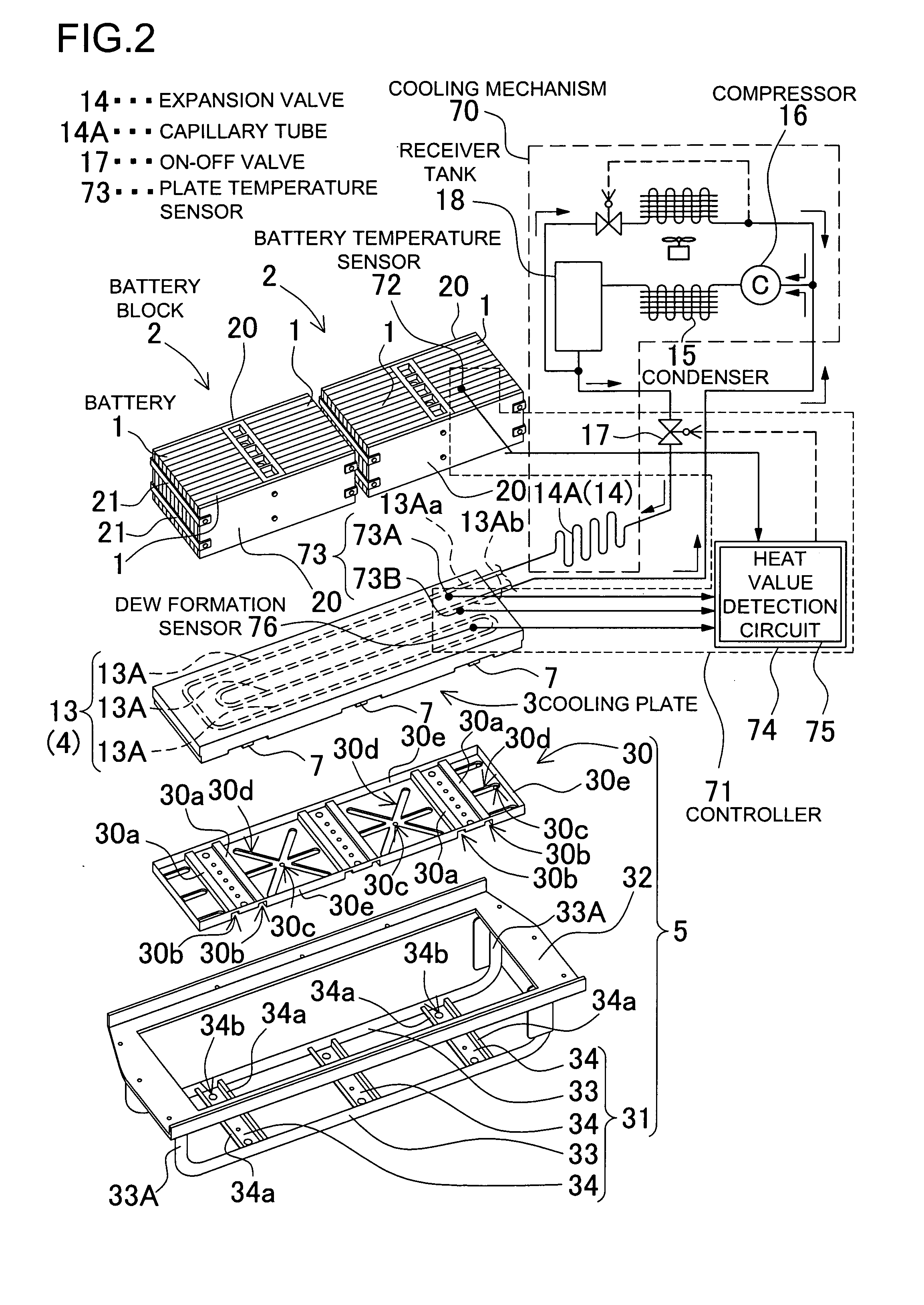
[0032]FIG. 2 through FIG. 5 show an electric power source used with a vehicle. FIG. 3 through FIG. 5 show a detail view of the electric power source illustrated in a schematic, exploded, perspective view in FIG. 2. The electric power source shown in these drawings includes: a battery block 2 composed of a rechargeable battery 1; a cooling plate 3 thermally coupled with and cooling the battery block 2; a cooling mechanism 70 for cooling the cooling plate 3; a controller 71 for controlling the cooling mechanism 70 to switch the cooling plate 3 into a cooled state and an uncooled state; and a frame structure 5 to which the cooling plate 3 is fixed. The electric power source forcibly cools the battery block 2 from a bottom face of the battery block by means of the cooling plate 3.

[0033]In regard to the cooling plate 3, a top surface plate 11 and a bottom plate 12 are interconnected at a periphery to define an interior portion as a sealed chamber 10. Incorporated in the sealed chamber 1...


PUM


Abstract

An electric power source used with a vehicle includes: a battery block composed of a rechargeable battery; a cooling plate thermally coupled with the battery block to cool the battery; a cooling mechanism for cooling the cooling plate; and a controller for controlling the cooling mechanism to switch the cooling plate into a cooled state and an uncooled state. The controller controls the cooling mechanism both in accordance with temperature of the battery block and temperature of the cooling plate, and switches the cooling plate into the cooled state and the uncooled state.

Description

BACKGROUND OF THE INVENTION[0001]1. Field of the Invention[0002]The present invention generally relates to an electric power source being used with an electric vehicle such as a hybrid car, and particularly to an electric power source for cooling a battery block by means of a cooling plate.[0003]2. Description of the Related Art[0004]The electric power source to be mounted on a hybrid car or the like is required of forcibly cooling a battery which will generate heat when the battery is charged and discharged at a large current. This is because temperature increase of the battery causes electrical characteristics of the battery to decrease as well as shortens a duration of life of the battery and further causes safety to be inhibited. In order to prevent such harmful results, there have been developed a power source in which a battery is cooled by means of air (JP 2006-252847-A) and a power source in which a battery is cooled by means of a cooling plate (Japanese Utility Model Regist...

Claims


Application Information

Patent Timeline
IPC IPC(8): H01M10/50H01M10/60H01M2/10
CPCH01M10/5004H01M10/5079H01M10/5032H01M10/5016H01M10/625H01M10/647H01M10/6569H01M10/613Y02E60/10
Inventor SHIMIZU, HIDEO
Owner SANYO ELECTRIC CO LTD
Why Eureka
Try Eureka