Fiber Architecture for Pi-Preforms

a fiber architecture and fiber technology, applied in the field of woven preforms, can solve the problems of inability to use metal bolts or rivets at the interface of such components, and inability to meet the needs of textiles and papermaking

Active Publication Date: 2009-10-01
ALBANY ENGINEERED COMPOSITES
View PDF56 Cites 50 Cited by
  • Summary
  • Abstract
  • Description
  • Claims
  • Application Information

AI Technical Summary

Benefits of technology

[0018]It is therefore a principal object of the invention to provide for ...

Problems solved by technology

Typically, however, they will not be of the same materials or have comparable physical, chemical thermal or other properties, since a usual objective sought in using composites in the first place is to achieve a combination of characteristics in the finished product that is not attainable through the use of one constituent material alone.
However, when tension is applied to the cured panel or the skin of the composite structure, loads at unacceptably low values resulted in “peel” forces which separate the stiffening element from the panel at their interface since the effective strength of the joint is that of the matrix material and not of the adhesive.
The use of metal bolts or rivets at the interface of such components is unacceptable because such additions at least partially destroy and weaken the integrity of composite structures themselves, add weight, and introduce differences in the coefficient of thermal expansion as between such elements and the surrounding material.
However, the expense involved is considerable and rarely is it desirable to have a weaving machine directed to creating a simple structure.
However, the prior-art pre...

Method used


Image

  • Fiber Architecture for Pi-Preforms
  • Fiber Architecture for Pi-Preforms
  • Fiber Architecture for Pi-Preforms

Examples


Embodiment Construction

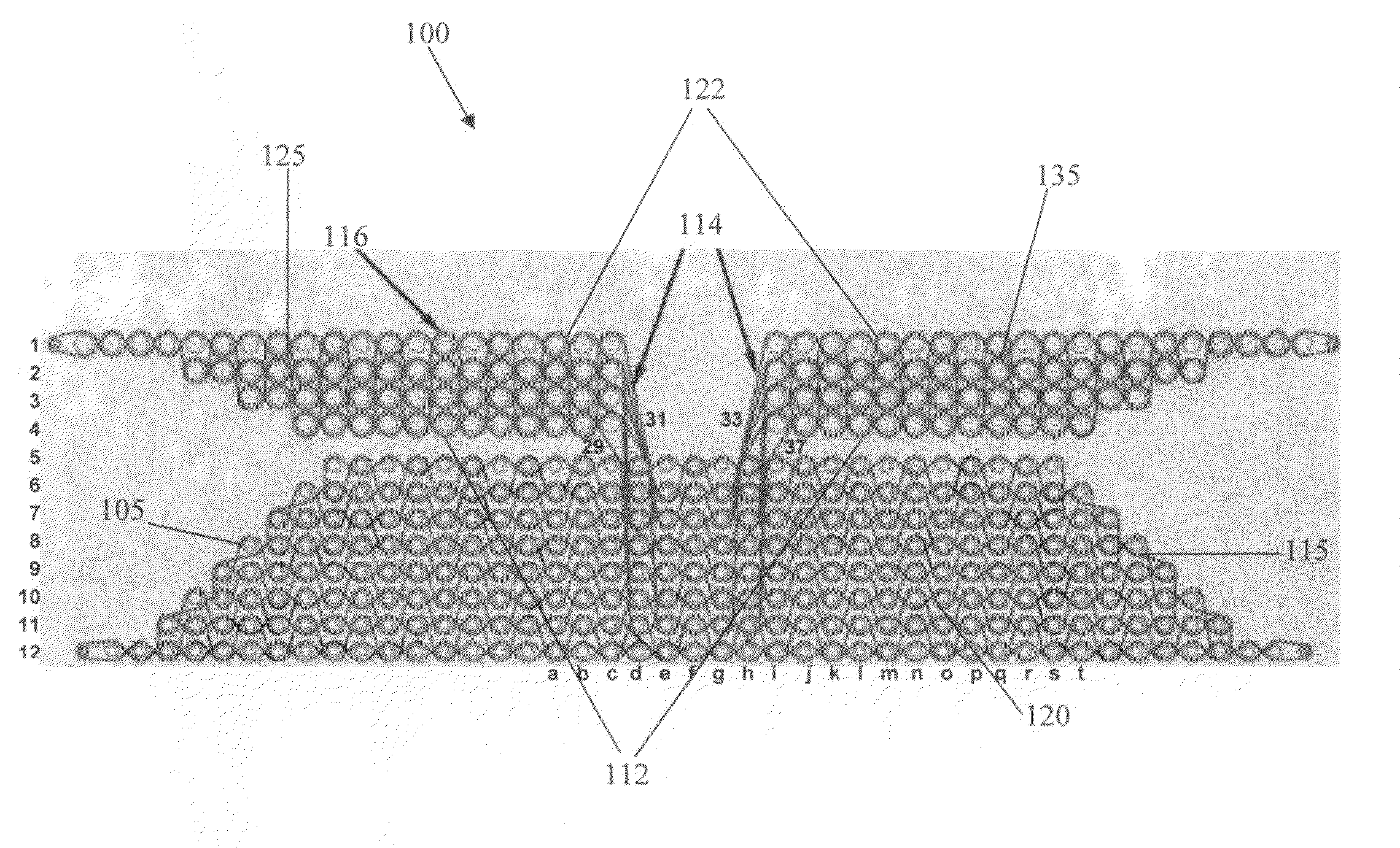
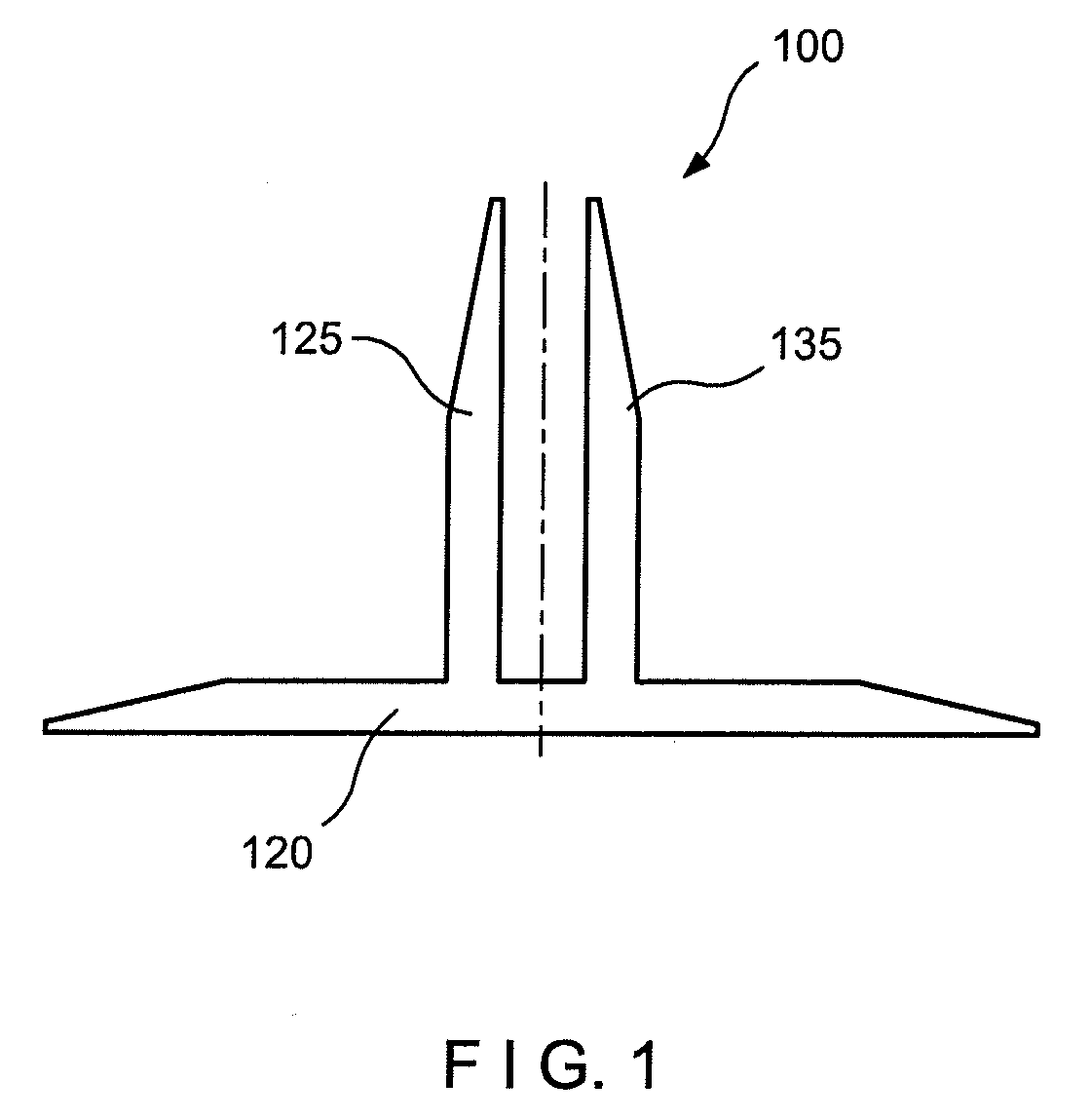
[0036]FIGS. 1, 4, 5a and 6 illustrate a preferred embodiment of a three-dimensional preform 100. Preform 100 is formed by weaving one or more fill fibers 114 in a pattern through a plurality of warp fibers 116, warp fibers 116 extending perpendicularly to the plane of the pattern. In FIGS. 4 and 6, the complete pattern used to form Pi-shaped preform 100 is illustrated, where fill fibers 114 are shown in the viewing plane, whereas warp fibers 116 are shown as perpendicular to the viewing plane. Fibers 114, 116 are shown as spaced apart in the schematic views of the architecture, though fibers 114, 116 are compacted together when actually woven into a completed preform 100.

[0037]Turning now to FIG. 4, all warp fibers 116 in preform 100 are generally parallel to each other, with slight undulations along the longitudinal length of each fiber 116, and are arranged in generally vertical columns. Preform 100 is preferably woven from materials used for typical composite structures, for exam...


PUM

PropertyMeasurementUnit
Lengthaaaaaaaaaa
Symmetryaaaaaaaaaa

Abstract

A woven preform for a reinforces composite material, which may be woven flat and folded into a shape. The preform has a three-dimensional weave architecture with fill fibers woven to provide layer-to-layer interlocking of layers of warp fiber as well as interlocking of fibers within each layer. At least two legs extend from a base, the base and legs each having at least two layers of warp fibers. The legs can be connected at a symmetrical or asymmetrical, distributed-column intersection, with an even or odd number of columns of warp fibers being located between the legs. The outer ends of the base and/or legs preferably have tapers formed from terminating layers of warp fibers in a stepped pattern.

Description

BACKGROUND OF THE INVENTION[0001]1. Field of the Invention[0002]This invention generally relates to woven preforms and particularly relates to woven preform used in a reinforced composite material, which can be woven flat and folded into its final shape without producing undesirable loops in the preform.[0003]2. Incorporation by Reference[0004]All patents, patent applications, documents, references, manufacturer's instructions, descriptions, product specifications, and product sheets for any products mentioned herein are incorporated herein by reference, and may be employed in the practice of the invention.[0005]3. Description of the Prior Art[0006]The use of reinforced composite materials to produce structural components is now widespread, particularly in applications where their desirable characteristics are sought of being light in weight, strong, tough, thermally resistant, self-supporting and adaptable to being formed and shaped. Such components are used, for example, in aerona...

Claims


Application Information

Patent Timeline
IPC IPC(8): D03D25/00D03D23/00
CPCB29C70/222B29D99/0014Y10S139/01D10B2505/02B29B11/16D03D25/005Y10T442/3195Y10T442/3203Y10T442/3179
Inventor GOERING, JONATHANOUELLETTE, KENNETH
Owner ALBANY ENGINEERED COMPOSITES
Why Eureka
Try Eureka