
Hot-Spot Wireless Access Exploiting Shadowing Diversity of Distributed Antennas

a distributed antenna and hotspot technology, applied in repeater circuits, frequency-division multiplexes, wireless commuication services, etc., can solve the problems of increasing the number of mobile devices a cell can support as well as the size of the cell, increasing the power consumption of the transmitting device, and limiting the capacity of the system. , to achieve the effect of maximizing the signal-to-leakage ratio (slr) ratio and improving the capacity of the system

Inactive Publication Date: 2009-10-01
MITSUBISHI ELECTRIC RES LAB INC
View PDF5 Cites 24 Cited by
  • Summary
  • Abstract
  • Description
  • Claims
  • Application Information

AI Technical Summary

Benefits of technology

[0011]A relaying antenna is selected to maximize a signal-to-leakage ratio (SLR) ratio of the distributed antenna system. Further, the capacity of the system is improved by allocating a signal power based on a pseudo-capacity criterion such that an average pseudo capacity of the distributed antenna system is maximized.

Problems solved by technology

However, the higher transmit power leads to increase of power consumption in the transmitting device.
Also, interference to other mobile device in the same frequency band is increased proportionally to the signal power.
In cellular spread-spectrum systems such as CDMA, where the mobile devices share a single frequency and are only separated by different spreading codes, the number of mobile devices that a cell can support as well as the size of the cell is typically limited by the amount of interference present in the cell.
The increased interference therefore results in decreased cell capacity and size.
Even in FDMA systems such as GSM where each mobile device in a cell uses a different frequency, interference is still present between different cells and reduces the amount of frequency reuse the network can support.

Method used


Image

  • Hot-Spot Wireless Access Exploiting Shadowing Diversity of Distributed Antennas
  • Hot-Spot Wireless Access Exploiting Shadowing Diversity of Distributed Antennas
  • Hot-Spot Wireless Access Exploiting Shadowing Diversity of Distributed Antennas

Examples


Embodiment Construction

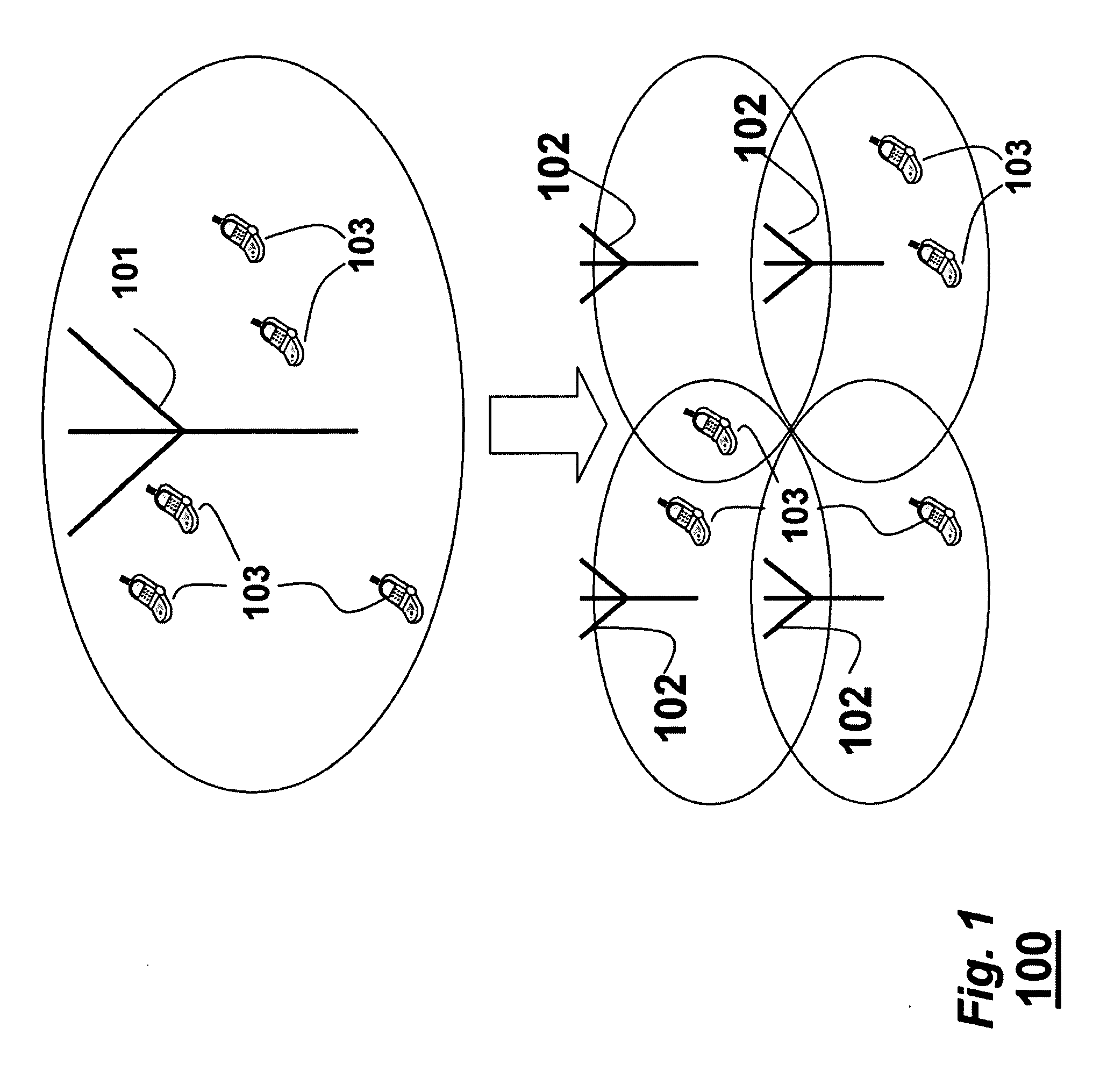
[0018]FIG. 1 shows a distributed antenna system (DAS) 100 used by embodiments of the invention. The system includes a set (one or more) of fixed antennas 102 suitable to relay a wireless signal to and from a set (one or more) of mobile device 103. The antennas 102 are connected to a common RF transceiver, e.g., a base station not shown, via a transport medium that provides wireless service within a relatively small geographic area or structure.

[0019]From time to time, antenna selection is performed for a mobile device 103. The mobile device 103 is the one which starts or continues to receive or transmit data packages through one of the antenna 102. The antenna selection could be performed once per communication session or for any or for every data package transmittal. The DAS 100 might have limited frequency band under limited space, e.g., in-door communications, data transmission in a wireless hot-spot football stadium.

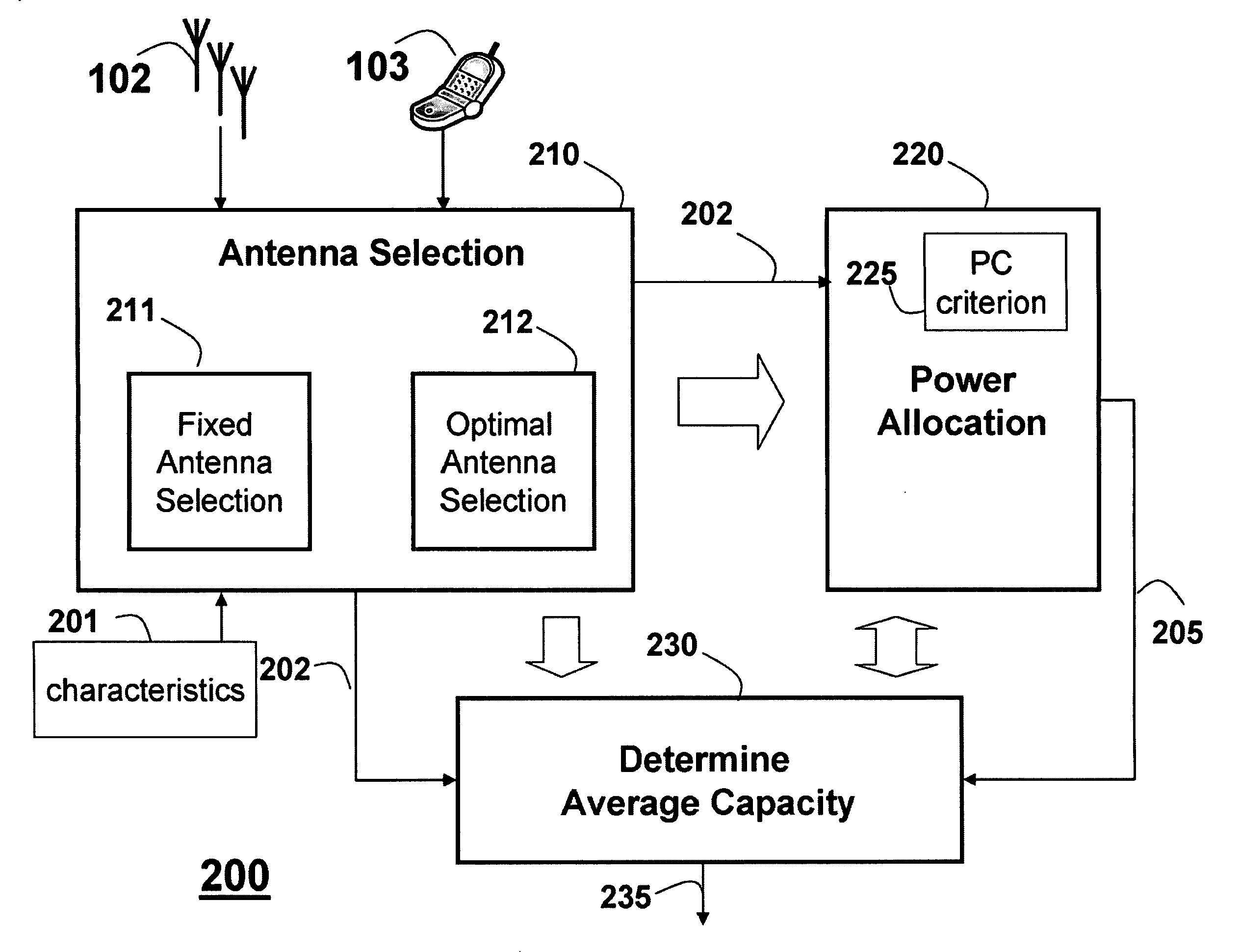
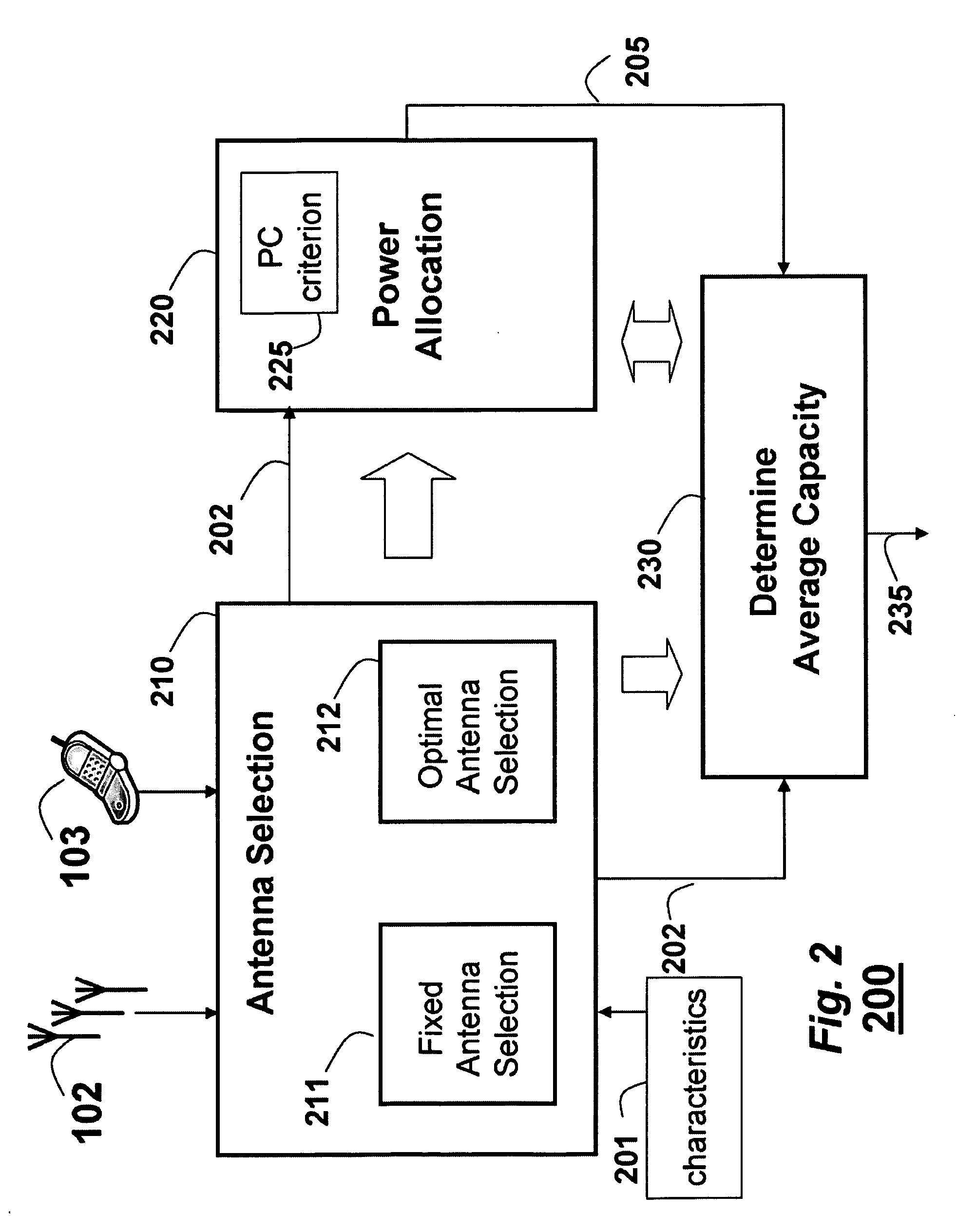
[0020]FIG. 2 show a system and a method 200 according to embodi...


PUM


Abstract

The embodiments of the invention describe method and system for maximizing capacity of a distributed antenna system. A relaying antenna is selected to maximize a signal-to-leakage ratio (SLR) ratio of the distributed antenna system. Further, the capacity of the system is improved by allocating a signal power based on a pseudo-capacity criterion such that an average pseudo capacity of the distributed antenna system is maximized.

Description

FIELD OF THE INVENTION[0001]This invention relates generally to hot-spot wireless access with distributed antennas, and more particularly to a system and method for selecting antennas and allocating desired signal power.BACKGROUND OF THE INVENTION[0002]A hot-spot is a venue that offers WiFi access. Hot-spot wireless access is required by number of mobile devices, e.g., a laptop, Wi-Fi phone, or other device suitable to access the Internet. Of the estimated 150 million laptops, 14 million personal digital assistants (PDAs), and other emerging Wi-Fi devices sold per year for the last few years, most include the Wi-Fi feature. One of the critical tasks of hot-spot wireless access is to serve mobile devices crowded in a small area while the available wireless spectrum is limited.[0003]Distributed Antenna System[0004]To improve the throughput of hot-spot wireless access, distributed antenna system has been utilized. A Distributed Antenna System (DAS) is a network of spatially separated a...

Claims


Application Information

Patent Timeline
IPC IPC(8): H04B7/14
CPCH04W52/46
Inventor LI, YEZHANG, JINYUN
Owner MITSUBISHI ELECTRIC RES LAB INC
Learn More