Al technical title is built by PatSnap Al team. It summarizes the technical point description of the patent document.
a technology of electrosurgical system and electrode, applied in the field of electrosurgical system, can solve the problems of electrical burns, bleeds, and the risk of certain types of patient injuries, and achieve the effect of increasing the functionality of the tool
Active Publication Date: 2009-10-01
APPL MEDICAL RESOURCES CORP
View PDF101 Cites 371 Cited by
Summary
Abstract
Description
Claims
Application Information
AI Technical Summary
This helps you quickly interpret patents by identifying the three key elements:
Problems solved by technology
Method used
Benefits of technology
[0019]At the same time, various embodiments of the surgical tools described herein can include different electrode configurations. I.e., while in one embodiment only the lower jaw is utilized to provide both coagulation and cutting functions, another embodiment can also employ the upper jaw element
Problems solved by technology
As bodily tissue, especially relatively highly vascularized tissue is cut during a surgical procedure, it tends to bleed.
Advantageously, unlike typical mechanical blade procedures, application of electrical energy to tissue tends to stop bleeding of the tissue.
Monopolar electrosurgical tools can be useful in certain procedures, but can include a risk of certain types of patient injuries such as electrical burns often at least partially attributable to functioning of the return electrode.
Even with the relatively focused surgical effects of
Method used
Image
Click on the blue label to locate the original text in one second.
Reading with bidirectional positioning of images and text.
Examples
Embodiment Construction
[0155]The following description is provided to enable any person skilled in the art to make and use the surgical tools and perform the methods described herein and sets forth the best modes contemplated by the inventors of carrying out their inventions. Various modifications, however, will remain apparent to those skilled in the art. It is contemplated that these modifications are within the scope of the present disclosure.
Electrosurgical System
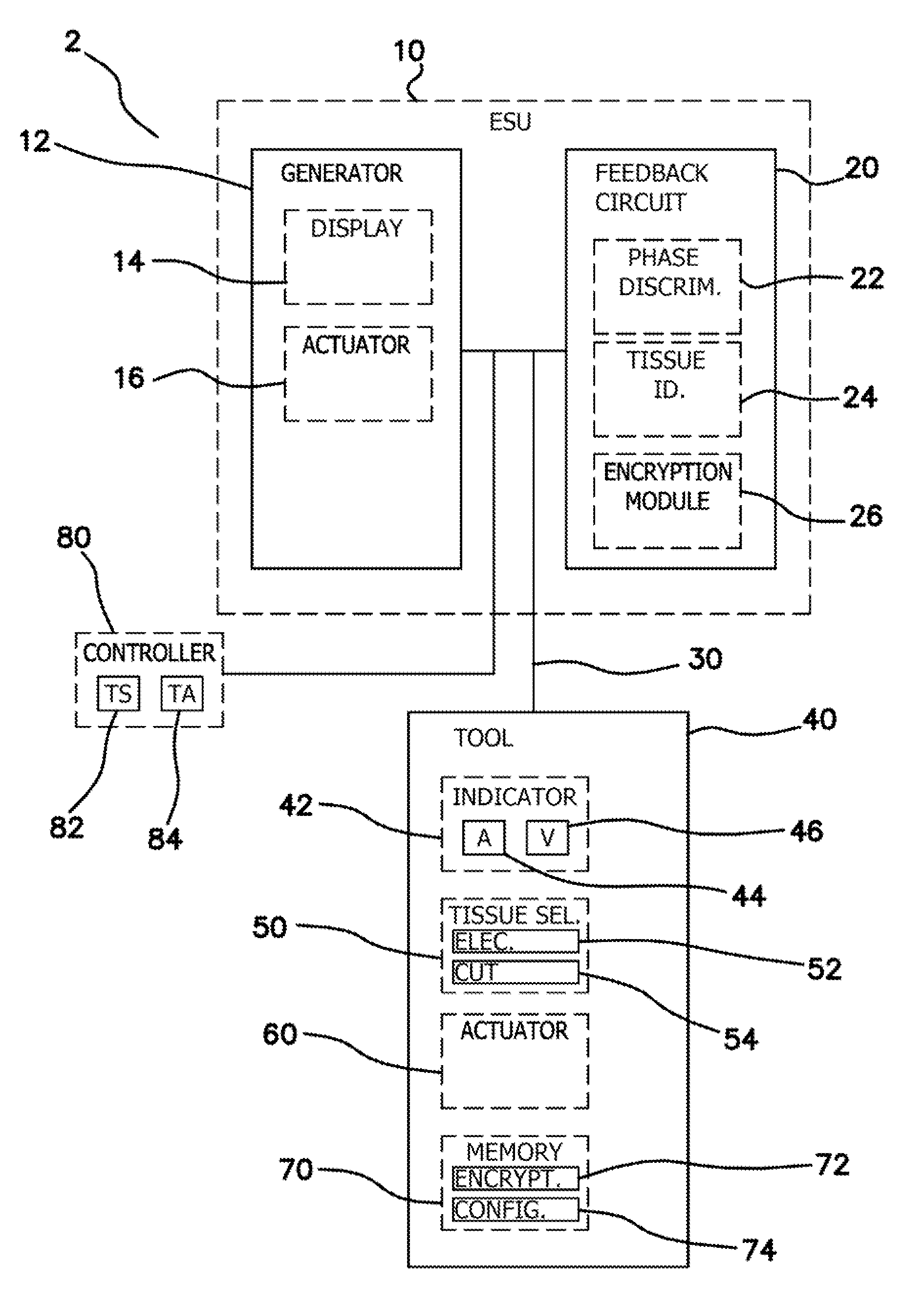
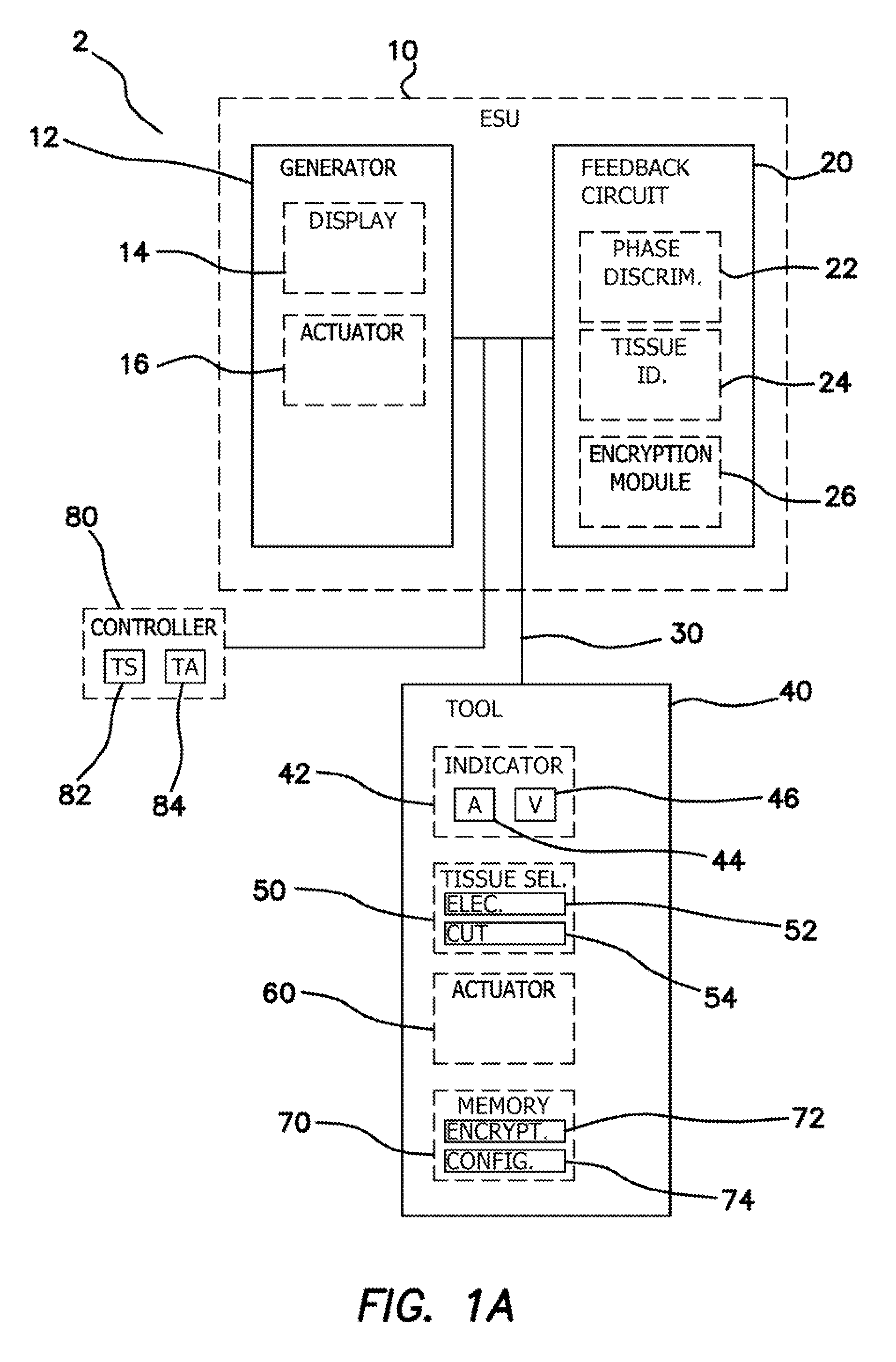
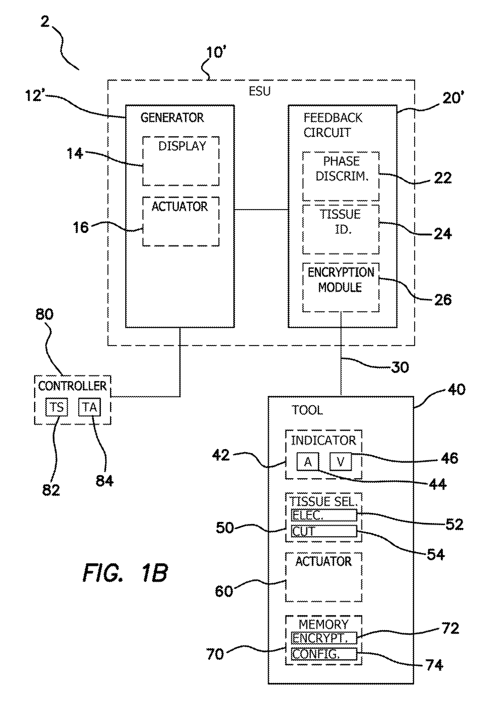
[0156]FIG. 1A illustrates a schematic diagram of an electrosurgical system 2. The electrosurgical system 2 can comprise an electrosurgical unit (ESU) 10 and an electrosurgical tool 40. The electrosurgical tool 40 can be electrically coupled to the electrosurgical unit 10. In some embodiments, an electronic coupler 30 such as an electrical wire, wire bundle, or cable can electrically couple the electrosurgical tool 40 to the ESU 10. In some embodiments, the electrosurgical system 2 can optionally further comprise an external tool controller 80...
PUM
Abstract
An electrosurgical system can include an electrosurgical generator, a feedback circuit or controller, and an electrosurgical tool. The feedback circuit can provide an electrosurgery endpoint by determining the phase end point of a tissue to be treated. The electrosurgical system can include more than one electrosurgical tool for different electrosurgical operations and can include a variety of user interface features and audio/visual performance indicators. The electrosurgical system can also power conventional bipolar electrosurgical tools and direct current surgical appliances.
Description
CROSS REFERENCE TO RELATED APPLICATIONS[0001]This application is a continuation of U.S. patent application Ser. No. 12 / 416,128, entitled “ELECTROSURGICAL SYSTEM”, filed Mar. 31, 2009, currently pending, which claims the benefit of U.S. Provisional Patent Application Ser. No. 61 / 040,980, entitled “FEEDBACK CONTROL MECHANISM FOR FUSING BIOLOGICAL TISSUE WITH HIGH FREQUENCY ELECTRICAL ENERGY”, filed Mar. 31, 2008; U.S. Provisional Patent Application Ser. No. 61 / 040,994, entitled “FUSING BIOLOGICAL TISSUE WITH HIGH FREQUENCY ELECTRICAL ENERGY”, filed Mar. 31, 2008; U.S. Provisional Patent Application Ser. No. 61 / 040,957, entitled “METHOD AND APPARATUS FOR BLOODLESS TISSUE DISSECTION”, filed Mar. 31, 2008; U.S. Provisional Patent Application Ser. No. 61 / 040,828, entitled “LAPAROSCOPIC BIPOLAR ELECTRICAL INSTRUMENT”, filed Mar. 31, 2008; U.S. Provisional Patent Application Ser. No. 61 / 040,890, entitled “APPARATUS AND METHOD FOR FUSION OF LIVING TISSUE”, filed Mar. 31, 2008; U.S. Provision...
Claims
Application Information
Patent Timeline
Application Date:The date an application was filed.
Publication Date:The date a patent or application was officially published.
First Publication Date:The earliest publication date of a patent with the same application number.
Issue Date:Publication date of the patent grant document.
PCT Entry Date:The Entry date of PCT National Phase.
Estimated Expiry Date:The statutory expiry date of a patent right according to the Patent Law, and it is the longest term of protection that the patent right can achieve without the termination of the patent right due to other reasons(Term extension factor has been taken into account ).
Invalid Date:Actual expiry date is based on effective date or publication date of legal transaction data of invalid patent.
Inventor FALKENSTEIN, ZORANCAPELLO, CHRISTOPHER J.JOHNSON, GARY M.GIANNESCHO, BENJAMIN A.TRAN, OLIVIA J.WIXEY, MATTHEW A.PROVONGVIENGKHAM, KENNIIPRAVONG, BOUNYAWATA, HARUYASUBECERRA, MATTHEW M.BRUSTAD, JOHN R.COHEN, ADAM J.HILAL, NABILPINGLETON, EDWARD D.HILAL, SAID S.HART, CHARLES C.WIKOFF, CHRIS R.