Artificial disc replacement device

Inactive Publication Date: 2009-10-01
K2M
View PDF63 Cites 13 Cited by
  • Summary
  • Abstract
  • Description
  • Claims
  • Application Information

AI Technical Summary

Benefits of technology

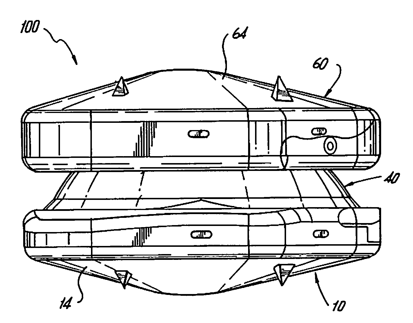
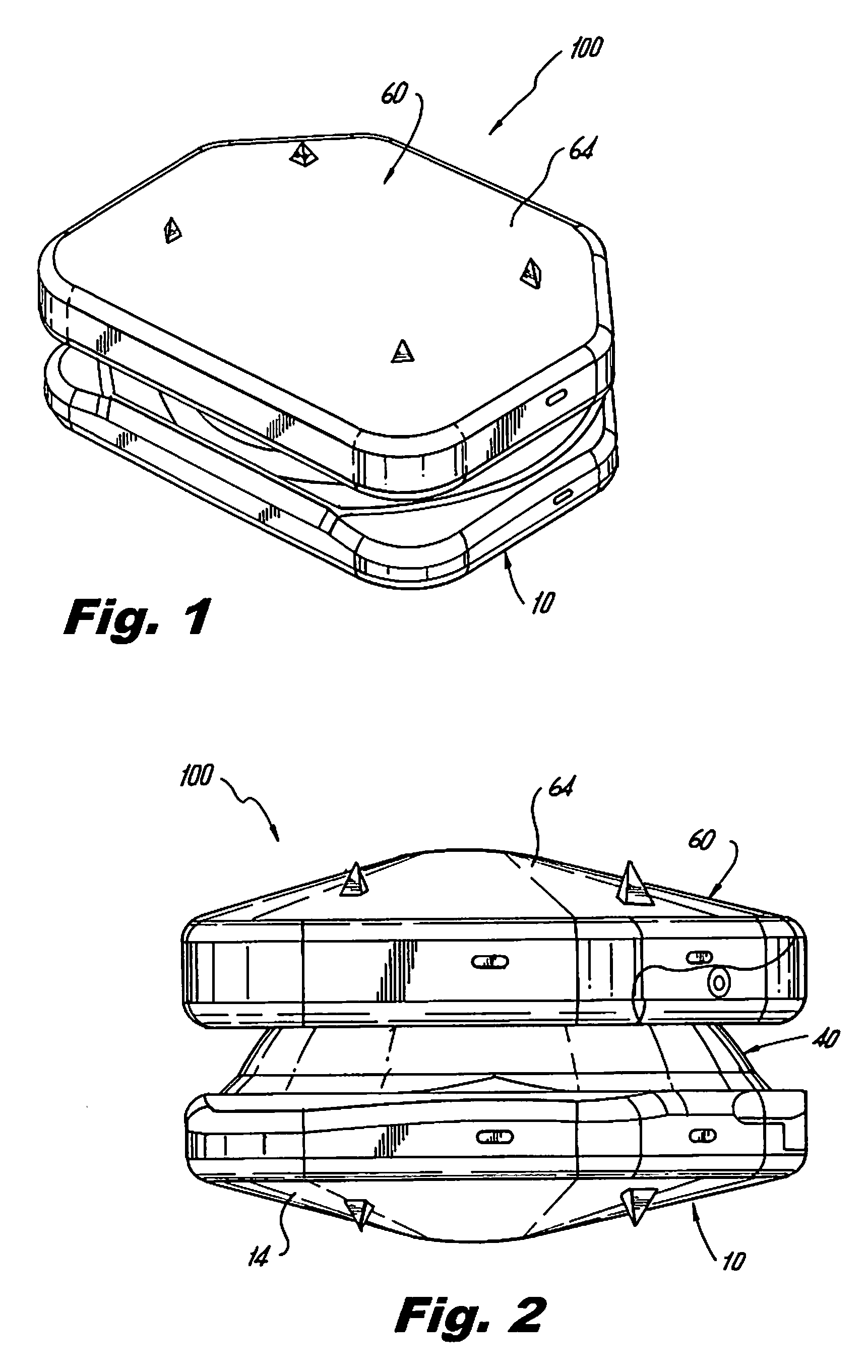
[0012]In an alternate embodiment, the disk is adapted for use in cervical procedures. In this embodiment, the dome of the support member is eccentric or asymmetric with respect to the axis extending through the opposing arms. Thus, when the cup pivots about the axis extending through the arms, the asymmetric configuration of the dome interacts with the cup causing the plate members of the disk to pivot and lift (i.e. increase the distance between the plate members).
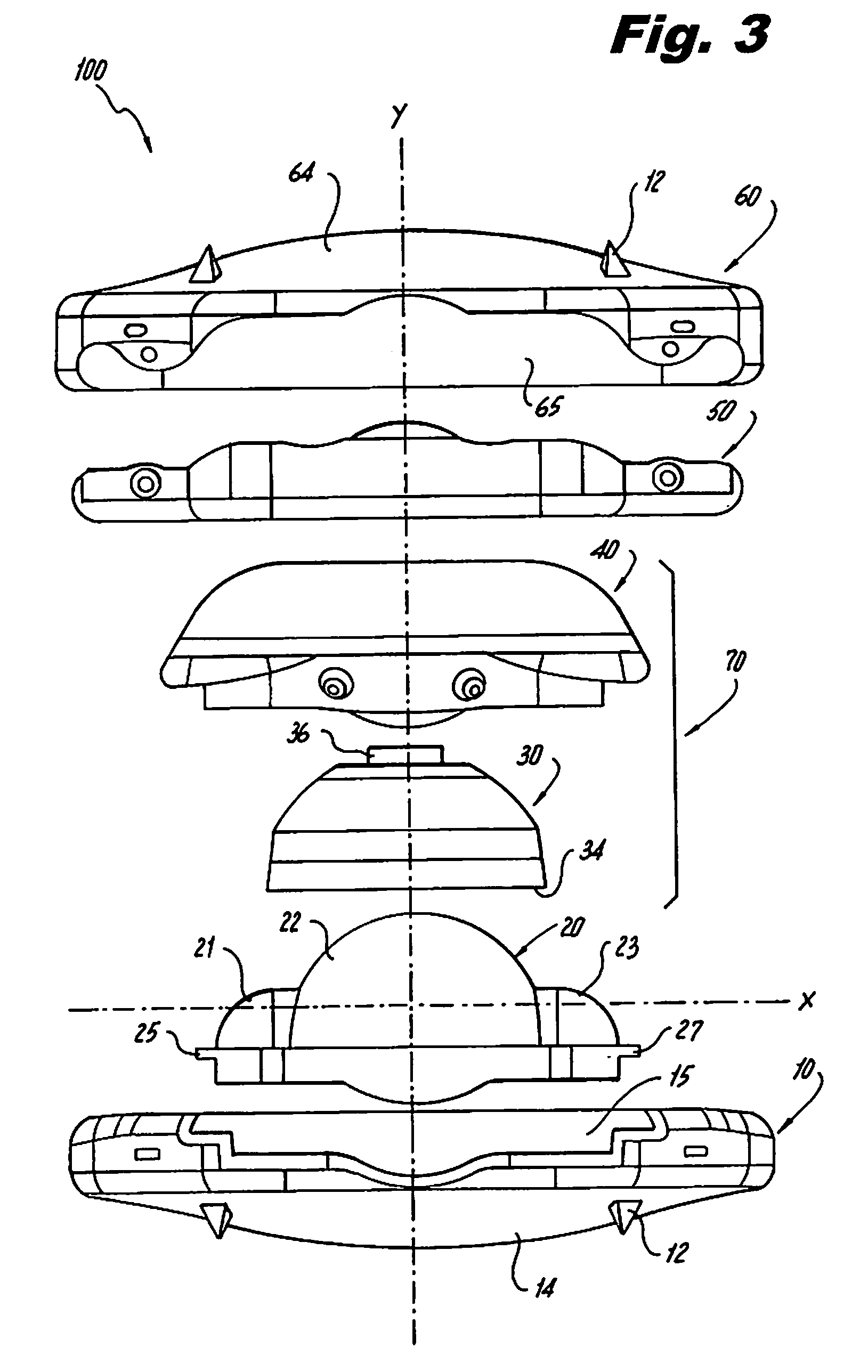
[0013]An installation tool and a method of installing the disk are also disclosed. The installation tool has a handle, a knob, and a shaft. At the distal end of the installation tool, a pair of opposing jaws or blade portions exists. The blade portions releasably engage the first and second plate members. An attachment portion is located at a distal end of the shaft for releasably engaging the pivoting assembly of the disk. With the first and second plate members attached to the blade portions and the pivoting assembly coupled to the attachment portion, the physician inserts the distal end of the installation tool between the adjacent vertebral bodies. Rotating the handle in one direction causes the shaft to translate distally through the installation tool. As the pivoting assembly moves distally, it engages inner surfaces of the blade portions urging them apart. Once the pivoting assembly is fully translated in the distal direction, the support member and the engagement member slide into openings in the respective first and second plate members, thereby securing the pivoting assembly between the first and second plate members and completing the assembly of the disk. Since the distraction of the adjacent vertebral bodies is performed prior to installing the pivoting assembly, this reduces the installation force necessary to install the disk. Thus, the potential trauma to the patient is reduced and any possibility of deforming the disk is also reduced.

Problems solved by technology

Excessive pressure or injuries to the nucleus can cause injury to the annulus, which is the outer ring that holds the disc together.
Eventually this can lead to damage of the nucleus pulposus.
The nucleus begins to lose its water content due to the damage; it begins to dry up.
Because of water loss, the discs lose some of their ability to act as a cushion.
This can lead to even more stress on the annulus and still more tears as the cycle repeats.
This results in a narrowing of the disc space between the two vertebrae.
This shift changes the way the facet joints work together and can cause problems in the facet joints as well.
In addition, the implantable device will have a limited amount of particulate debris so as to reduce complications over the useful life of the device.

Method used


Image

  • Artificial disc replacement device
  • Artificial disc replacement device
  • Artificial disc replacement device

Examples


Embodiment Construction

[0028]Particular embodiments of the present disclosure will be described herein with reference to the accompanying drawings. In the drawings and in the description that follows, the term “proximal,” will refer to the end of a device or system that is closest to the operator, while the term “distal” will refer to the end of the device or system that is farthest from the operator. In addition, the term “cephalad” is used in this application to indicate a direction toward a patient's head, whereas the term “caudad” indicates a direction toward the patient's feet. Further still, for the purposes of this application, the term “medial” indicates a direction toward the middle of the body of the patient, whilst the term “lateral” indicates a direction toward a side of the body of the patient (i.e., away from the middle of the body of the patient). The term “posterior” indicates a direction toward the patient's back, and the term “anterior” indicates a direction toward the patient's front.

[0...


PUM


Abstract

An artificial disk replacement device includes opposing plate members with a pivoting assembly disposed therebetween. The pivoting assembly allows the plate members to pivot relative to each other in a first direction, but inhibit movement of the plate members in a second direction. The plate members may be installed prior to installing the pivoting assembly. An installation tool for use with the artificial disk replacement device is also disclosed.

Description

CROSS-REFERENCE TO RELATED APPLICATIONS[0001]This application claims priority to, and the benefit of, U.S. Provisional Patent Application Ser. No. 61 / 070,126, filed Mar. 20, 2008, the entire contents of which are hereby incorporated by reference.BACKGROUND[0002]1. Technical Field[0003]This application relates to a device for use in orthopedic spine surgery. In particular, the present invention relates to an artificial disc replacement device that replaces a damaged or diseased intervertebral disc.[0004]2. Background of Related Art[0005]The human spine is composed of thirty-three vertebrae at birth and twenty-four as a mature adult. Between each pair of vertebrae is an intervertebral disc, which maintains the space between adjacent vertebrae and acts as a cushion under compressive, bending, and rotational loads and motions. A healthy intervertebral disc has a great deal of water in the nucleus pulposus, which is the center portion of the disc. The water content gives the nucleus a sp...

Claims


Application Information

Patent Timeline
IPC IPC(8): A61F2/44
CPCA61F2/4425A61F2/4611A61F2002/30367A61F2002/30387A61F2002/30604A61F2002/3065A61F2220/0033A61F2002/30841A61F2002/30934A61F2002/443A61F2002/4627A61F2002/4628A61F2220/0025A61F2002/3082
Inventor THEOFILOS, CHARLESENGLAND, GEORGE
Owner K2M
Why Eureka
Try Eureka