Vehicle drive device controller

a technology of drive device and controller, which is applied in the direction of battery/cell propulsion, instrumentation, etc., can solve the problems of further miniaturization of electric motors and improved fuel consumption, and achieve the effects of low output torque, smooth change of drive torque, and quick chang

Inactive Publication Date: 2009-10-01
TOYOTA JIDOSHA KK
View PDF11 Cites 49 Cited by
  • Summary
  • Abstract
  • Description
  • Claims
  • Application Information

AI Technical Summary

Benefits of technology

[0088]More preferably, the drive apparatus establishes the total gear ratio based on the gear ratio of the differential portion and the gear ratio of the shifting portion. With such an operation, the use of the gear ratio of the shifting portion results in capability of obtaining the drive power in a wide range. Alternately, with the shifting portion including a reduction speed transmission with a gear ratio greater than “1”, the second electric motor may suffice to provide a low output torque with respect to that of the output shaft of the shifting portion. This enables the second electric motor to be miniaturized. Moreover, the differential portion and the shifting portion constitute the continuously variable shifting portion with the differential portion placed in the differential state, and the differential portion and the shifting portion constitute the step variable transmission with the differential portion placed in the non-differential state.
[0089]The shifting portion is the step variable automatic transmission. With the step variable automatic transmission, the total gear ratio can be stepwise changed with shifting of the shifting portion, capable of being changed quicker than the case where the total gear ratio is continuously changed. Accordingly, the drive apparatus functions as the continuously variable transmission to smoothly change the drive torque and to stepwise change the gear ratio for rapidly obtaining the drive torque.

Problems solved by technology

This suppresses a loss in conversion efficiency between a drive power and electric energy occurring when the continuously variable shifting portion is rendered operative to electrically change the gear ratio, resulting in improved fuel consumption.
This minimizes a maximal value of electric energy to be generated by the electric motor, resulting in a further miniaturization of the electric motor or the vehicle drive apparatus including such an electric motor.

Method used


Image

  • Vehicle drive device controller
  • Vehicle drive device controller
  • Vehicle drive device controller

Examples


embodiment 1

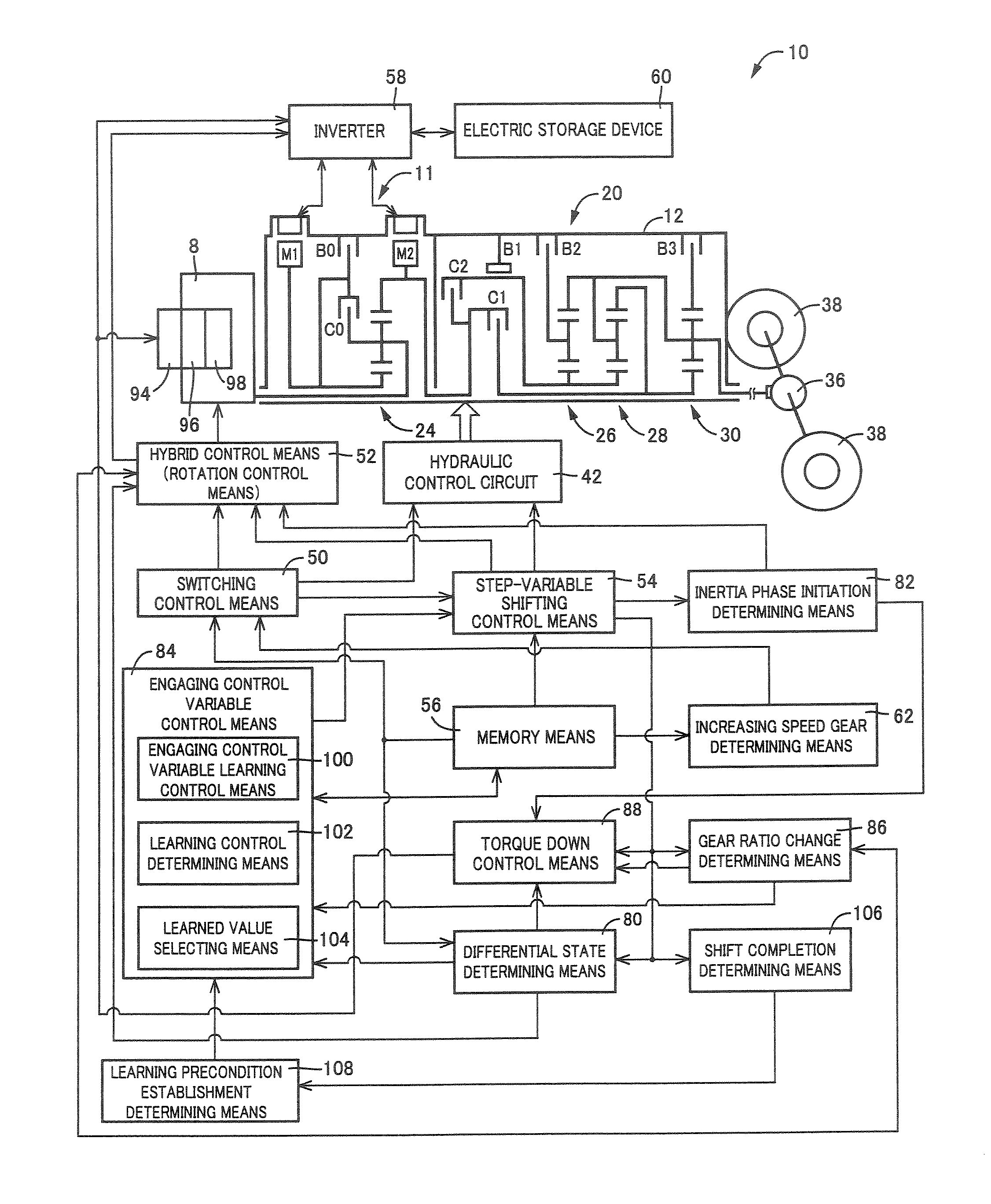
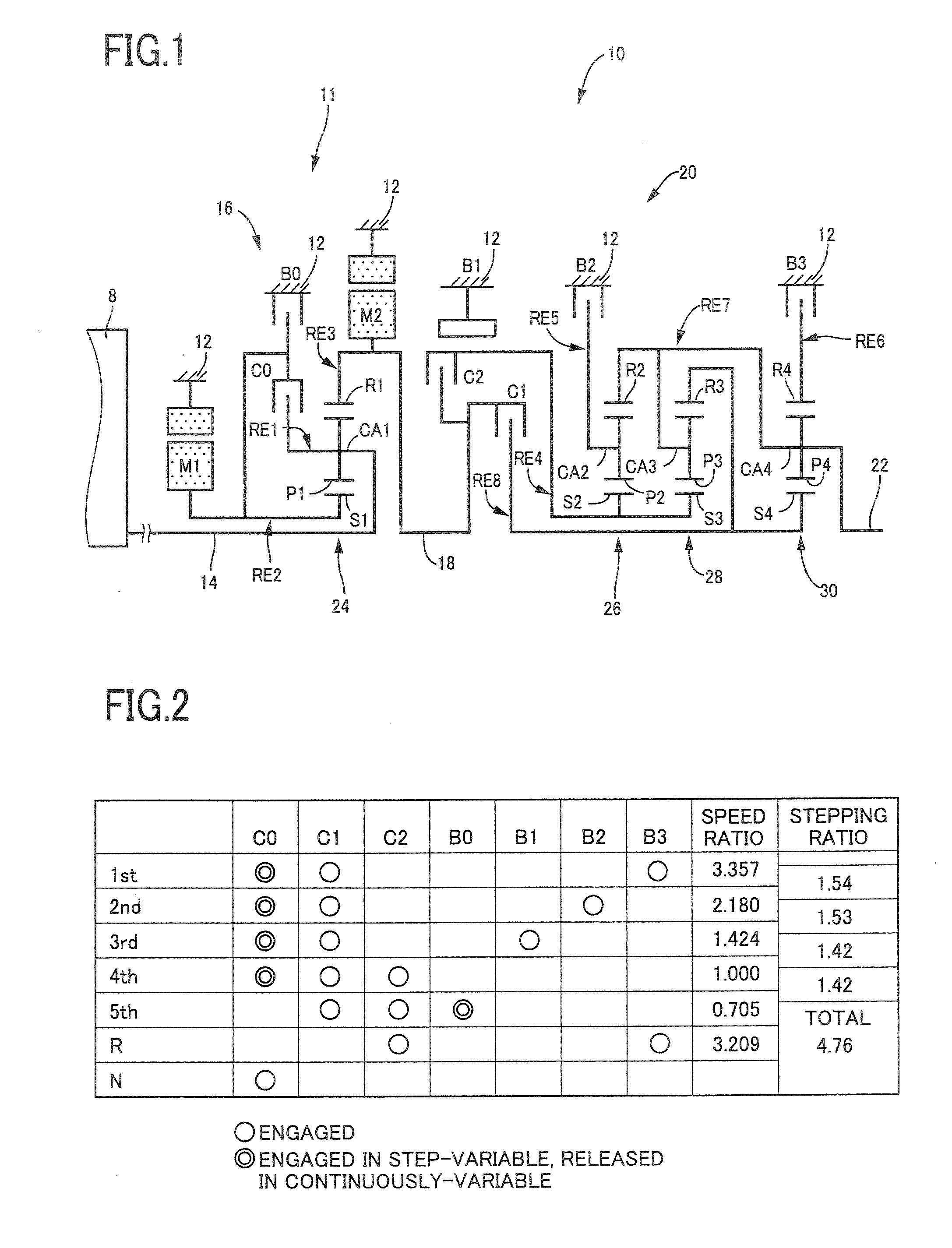
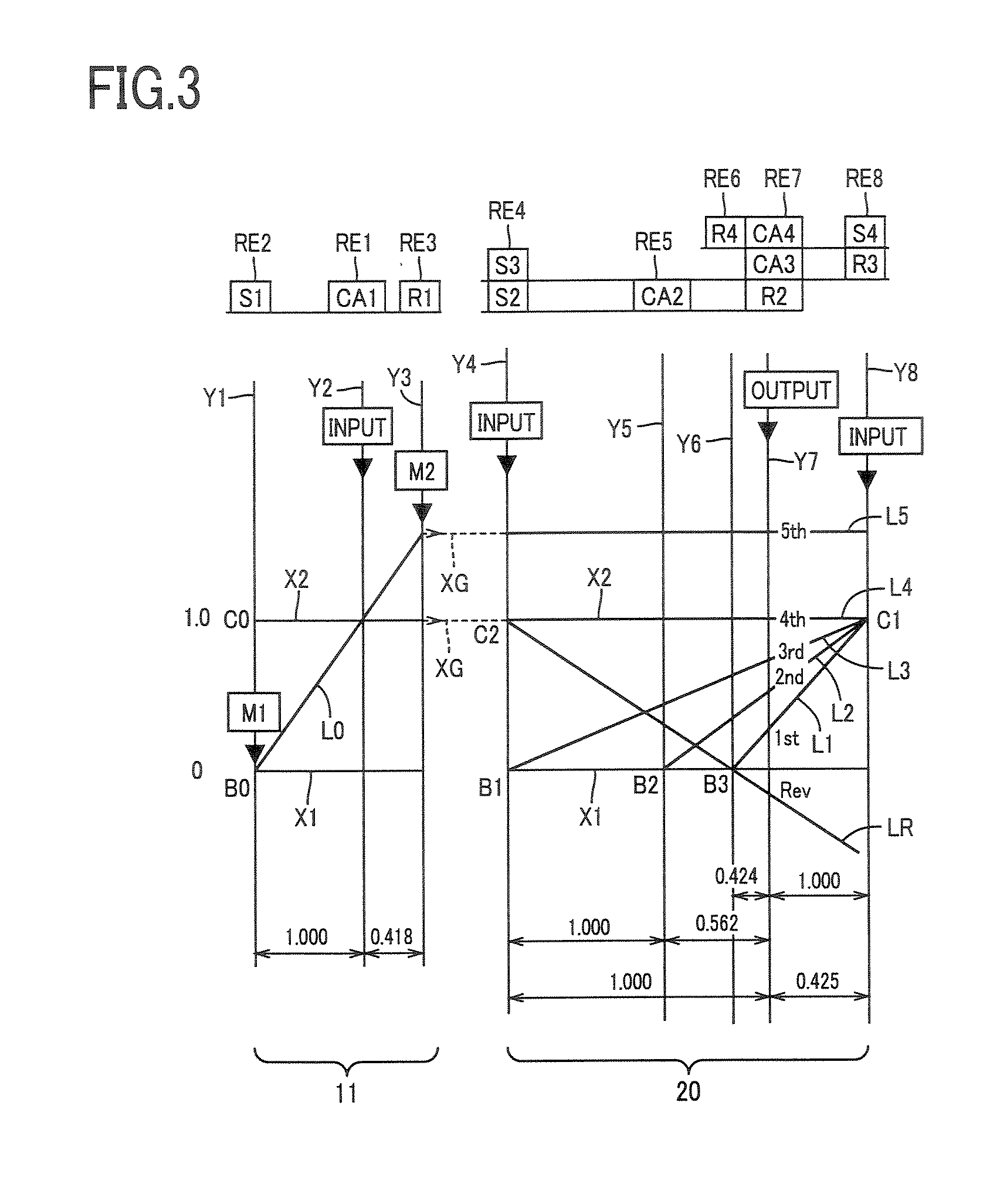
[0133]FIG. 1 is a skeleton view explaining a shifting mechanism i.e., transmission mechanism 10 constructing a part of a drive apparatus of a hybrid vehicle according to one embodiment of the present invention. The transmission mechanism i.e., shifting mechanism 10 includes an input shaft 14, a differential portion 11, an automatic shifting portion 20, and an output shaft 22 all coaxially disposed in a transmission case 12 (hereinafter briefly referred to as “case 12”) as a non-rotatable member fixed to a vehicle body. The input shaft 14 as an input rotation member is fixed to the case 12. The differential portion 11 functioning as the continuously variable shifting portion is connected to the input shaft 14 directly or indirectly via a pulsation absorbing damper (vibration damping device) not shown. The automatic shifting portion 20 i.e., the automatic shifting portion functioning as a step variable type transmission is disposed between the differential mechanism 11 and the output ...

embodiment 2

[0397]FIG. 20 is a skeleton view explaining structure of a shifting mechanism 70 according to another embodiment of the present invention. FIG. 21 is an operation Table indicating a relation between a shifting position of the shifting mechanism 70, and operation combinations of hydraulic-type friction engaging devices used therefor. FIG. 22 is a collinear chart explaining a shifting operation of the shifting mechanism 70.

[0398]Like the illustrated embodiment described above, the shifting mechanism 70 comprises the differential portion 11 including the first electric motor M1, the power distributing mechanism 16 and the second electric motor M2, and an automatic shifting portion 72 with three forward-gear positions connected to the differential portion 11 and the output shaft 22 in series via the transmitting member 18. The power distributing mechanism 16 includes the first planetary gear unit 24 of the single pinion type having a given speed ratio ρ1 of, for instance, about 0.418, t...

embodiment 3

[0412]FIG. 23 shows an example a seesaw type switch 44 (hereinafter referred to as “switch 44”), acting as a shifting-state manual selection device, which is installed on a vehicle for a vehicle driver to manually operate. The switch 44 allows manual operation to cause the power distributing mechanism 16 to be selectively placed in the differential state and the non-differential state (locked state), that is, the continuously variable shifting state and the step variable shifting state of the shifting mechanism 10. The switch 44 allows the vehicle to run in a shifting state desired by the vehicle driver. The switch 44 has a continuously variable shift running command button with a display “CONTINUOUSLY VARIABLE”, representing a continuously variable shift running mode, and a step variable shift running command button with a display “STEP VARIABLE” representing a step variable shift running mode. Upon depression of the vehicle driver on one of these buttons, the shifting mechanism 10...


PUM


Abstract

A control device for a vehicle drive apparatus that includes a differential mechanism and an electric motor provided in the differential mechanism, which can be miniaturized in structure with improved fuel economy and enabling suppression of occurrence in switching shocks. With a provision of a switching clutch or a switching brake, a shifting mechanism is placed in either a continuously variable shifting state or a step variable shifting state. During a shifting of an automatic shifting portion, an engaging control variable control alters a method of learning an engaging pressure. This allows a rotation speed of a transmitting member to achieve a given variation during the shifting, depending on a continuously variable shifting state and a non-continuously variable shifting state, for thereby providing a balance between an improvement in a feeling and a suppressing of shifting shocks.

Description

TECHNICAL FIELD[0001]The present invention relates to a drive apparatus for vehicle having a differential mechanism, operative to perform a differential action, and an electric motor and, more particularly, to a technology of miniaturizing an electric motor or the like and a shifting control technology.BACKGROUND ART[0002]There has heretofore been known a drive apparatus of a vehicle including a differential mechanism through which an output of a drive power source, such as an engine or the like, is distributed to a first electric motor and an output member, and a second electric motor disposed between the output member and drive wheels. Such drive apparatus for a hybrid vehicle is disclosed for example in Patent Publication 1. The drive apparatus includes a differential mechanism being comprised of a planetary gear unit i.e., gear set and performing as the differential action for mechanically transmitting a major part of power outputted from the engine to drive wheels. A remaining ...

Claims


Application Information

Patent Timeline
Patent Type & Authority Applications(United States)
IPC IPC(8): B60W20/00G06F19/00G06F7/00F16H61/04B60K6/365B60K6/387B60K6/445B60K6/547B60L50/16
CPCB60K6/365B60K6/387B60K6/445B60K6/547B60W10/08B60W10/115Y02T10/6239F16H3/728F16H61/061F16H2037/0873F16H2061/0087F16H2200/0047F16H2200/2012B60W20/00B60L15/20B60L2240/421B60L2240/423B60L2240/441B60L2240/443B60L2240/486B60L2240/507B60L2260/26B60L2270/145B60L50/16B60L50/61Y02T10/62Y02T10/64Y02T10/70Y02T10/7072Y02T10/72B60W20/10B60W20/30
Inventor TABATA, ATSUSHIINOUE, YUJIKAMADA, ATSUSHI
Owner TOYOTA JIDOSHA KK
Why Eureka
Try Eureka