
Method and apparatus for optimizing an optical proximity correction model

Inactive Publication Date: 2009-10-01
GLOBALFOUNDRIES US INC
View PDF4 Cites 15 Cited by
  • Summary
  • Abstract
  • Description
  • Claims
  • Application Information

AI Technical Summary

Problems solved by technology

The process of generating an OPC model is time intensive and expensive.
Techniques for evaluating OPC models involve intensively manual processes that are time consuming and prone to errors and / or omissions.
It is difficult to correlate the optical parameters of the calibration sites to those of the validation sites to allow the construction of an OPC model that adequately covers the design space expected in the actual design.

Method used


Image

  • Method and apparatus for optimizing an optical proximity correction model
  • Method and apparatus for optimizing an optical proximity correction model
  • Method and apparatus for optimizing an optical proximity correction model

Examples


Embodiment Construction

[0021]One or more specific embodiments of the disclosed subject matter will be described below. It is specifically intended that the disclosed subject matter not be limited to the embodiments and illustrations contained herein, but include modified forms of those embodiments including portions of the embodiments and combinations of elements of different embodiments as come within the scope of the following claims. It should be appreciated that in the development of any such actual implementation, as in any engineering or design project, numerous implementation-specific decisions must be made to achieve the developers' specific goals, such as compliance with system-related and business related constraints, which may vary from one implementation to another. Moreover, it should be appreciated that such a development effort might be complex and time consuming, but would nevertheless be a routine undertaking of design, fabrication, and manufacture for those of ordinary skill having the b...


PUM


Abstract

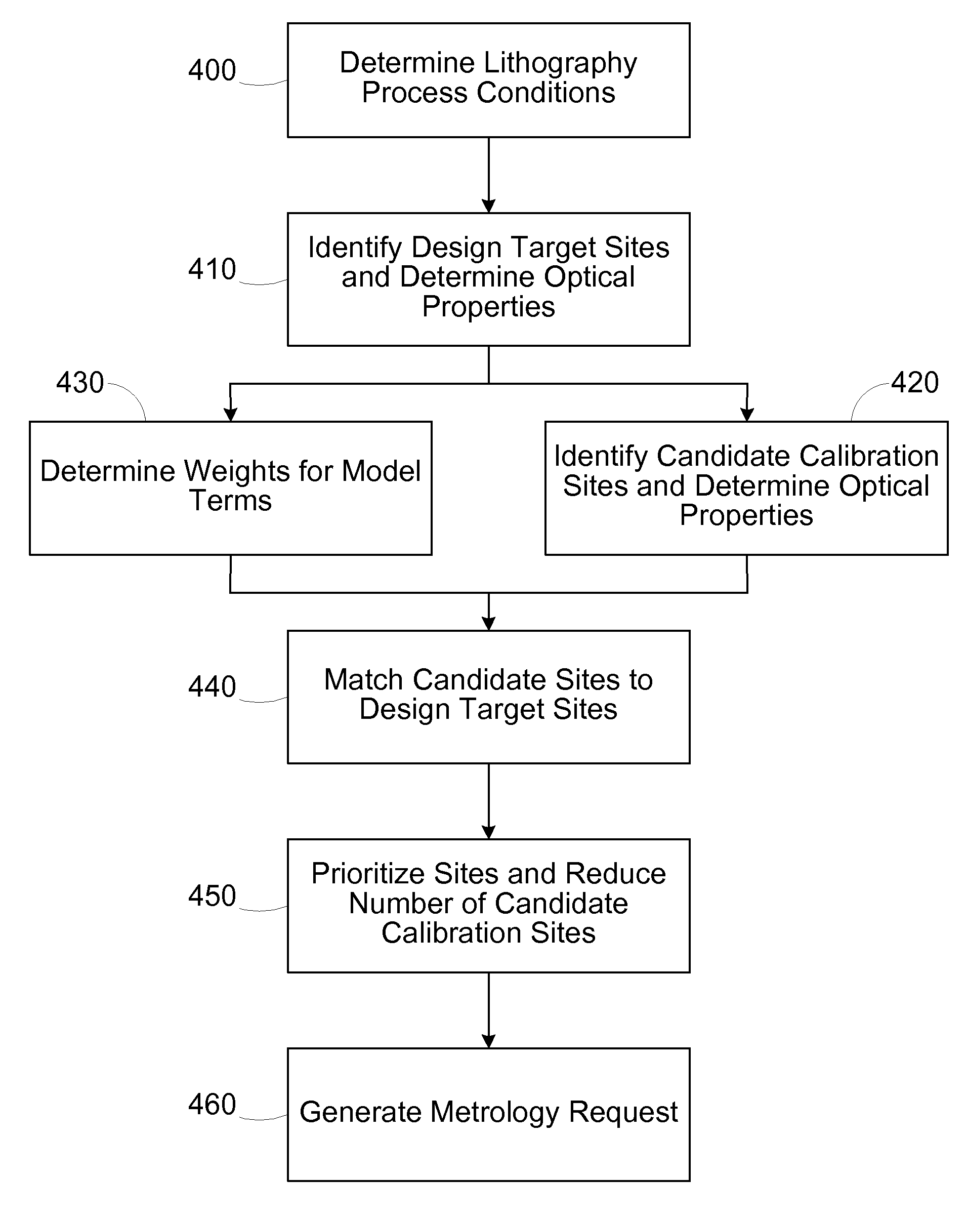
A method includes receiving optical profiles for a plurality of design target features associated with an integrated circuit device and optical profiles for a plurality of test features. An optical proximity correction (OPC) model including a plurality of terms is defined. Each term relates to at least one parameter in the optical profiles. A subset of the model terms is identified as being priority terms. Parameters of the optical profiles of the test features are matched to parameters of the optical profiles of the design target features using the priority terms to generate a set of matched test features. A metrology request is generated to collect metrology data from a test wafer having formed thereon at least a first subset of the matched test features and a second subset of the design target features.

Description

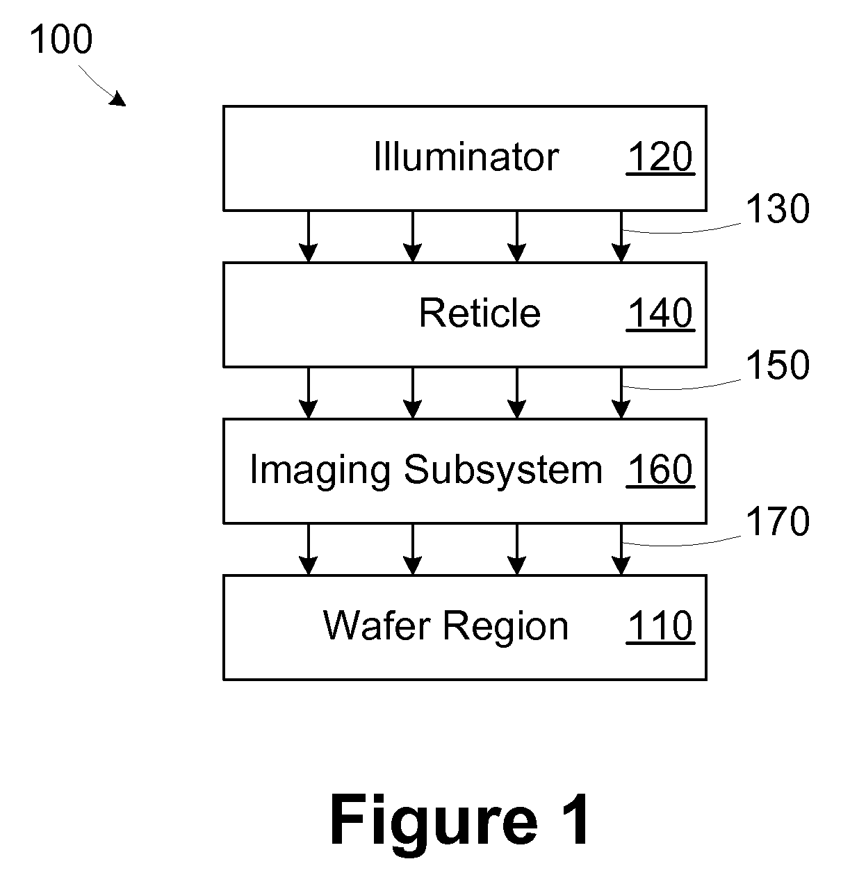
CROSS-REFERENCE TO RELATED APPLICATIONS[0001]Not applicable.BACKGROUND[0002]The disclosed subject matter relates generally to integrated circuit manufacturing and, more particularly, to a method and apparatus for optimizing an optical proximity correction model.[0003]The formation of various integrated circuit (IC) structures on a wafer often relies on lithographic processes, sometimes referred to as photolithography, or simply lithography. As is well known, lithographic processes can be used to transfer a pattern of a reticle to a wafer.[0004]For instance, patterns can be formed from a photoresist layer disposed on the wafer by passing light energy through a mask having an arrangement to image the desired pattern onto the photoresist layer. As a result, the pattern is transferred to the photoresist layer. In areas where the photoresist is sufficiently exposed, and after a development cycle, the photoresist material becomes soluble such that it can be removed to selectively expose a...

Claims


Application Information

Patent Timeline
IPC IPC(8): G06F17/50
CPCG03F1/36G03F1/144
Inventor KIM, HUNG-EILLEE, EUN-JOOSPENCE, CHRISTOPHER A.
Owner GLOBALFOUNDRIES US INC
Learn More