
High frequency deflection measurement of IR absorption

a high frequency deflection and absorption technology, applied in the field of high-localized infrared (ir) spectra, can solve the problems of insufficient optical power density and/or modulation rate, expensive and rare facilities, etc., and achieve the effect of suppressing background absorption sources, rapid and automated scanning, and convenient operation

Active Publication Date: 2009-10-01
BRUKER NANO INC
View PDF1 Cites 79 Cited by
  • Summary
  • Abstract
  • Description
  • Claims
  • Application Information

AI Technical Summary

Benefits of technology

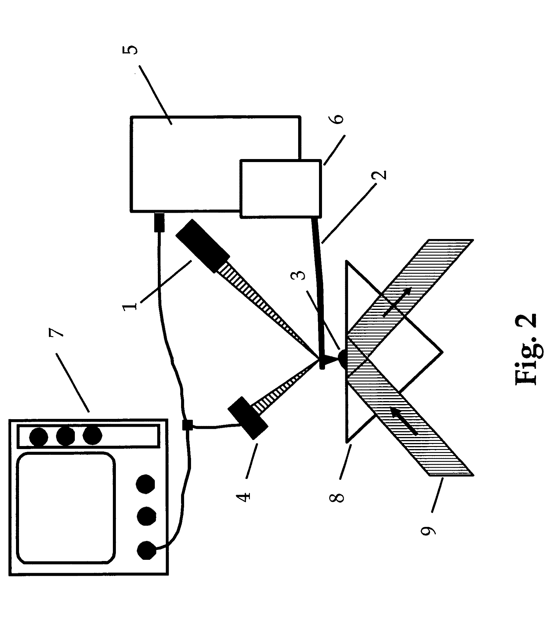
[0011]This invention is a novel benchtop instrument that can measure and map information about a sample's chemical composition with resolution down to the micron and nanometer scale. These measurements are enabled by a specialized Atomic Force Microscope (AFM) that provides highly localized Infrared (IR) spectra and absorption on a sample surface utilizing an Atomic Force Microscope (AFM). The instrument employs a benchtop source of variable wavelength infrared (IR) radiation that is broadly and continuously tunable over the “fingerprint region” that allows for highly sensitive discrimination and even identification of materials. (The fingerprint region has varying definitions in the literature, but covers wavelength ranges from roughly 7 to 17 um, with the richest region for chemical information being above 10 um.)
[0013]The current invention enables the reproducible measurement of broadband infrared spectra at highly localized points on a sample using an apparatus that is both portable and affordable. It overcomes the key limitations of the prior art which provided either very narrow band spectra or required expensive and rare facilities like the Free Electron Laser, or had insufficient optical power density and / or modulation rates.
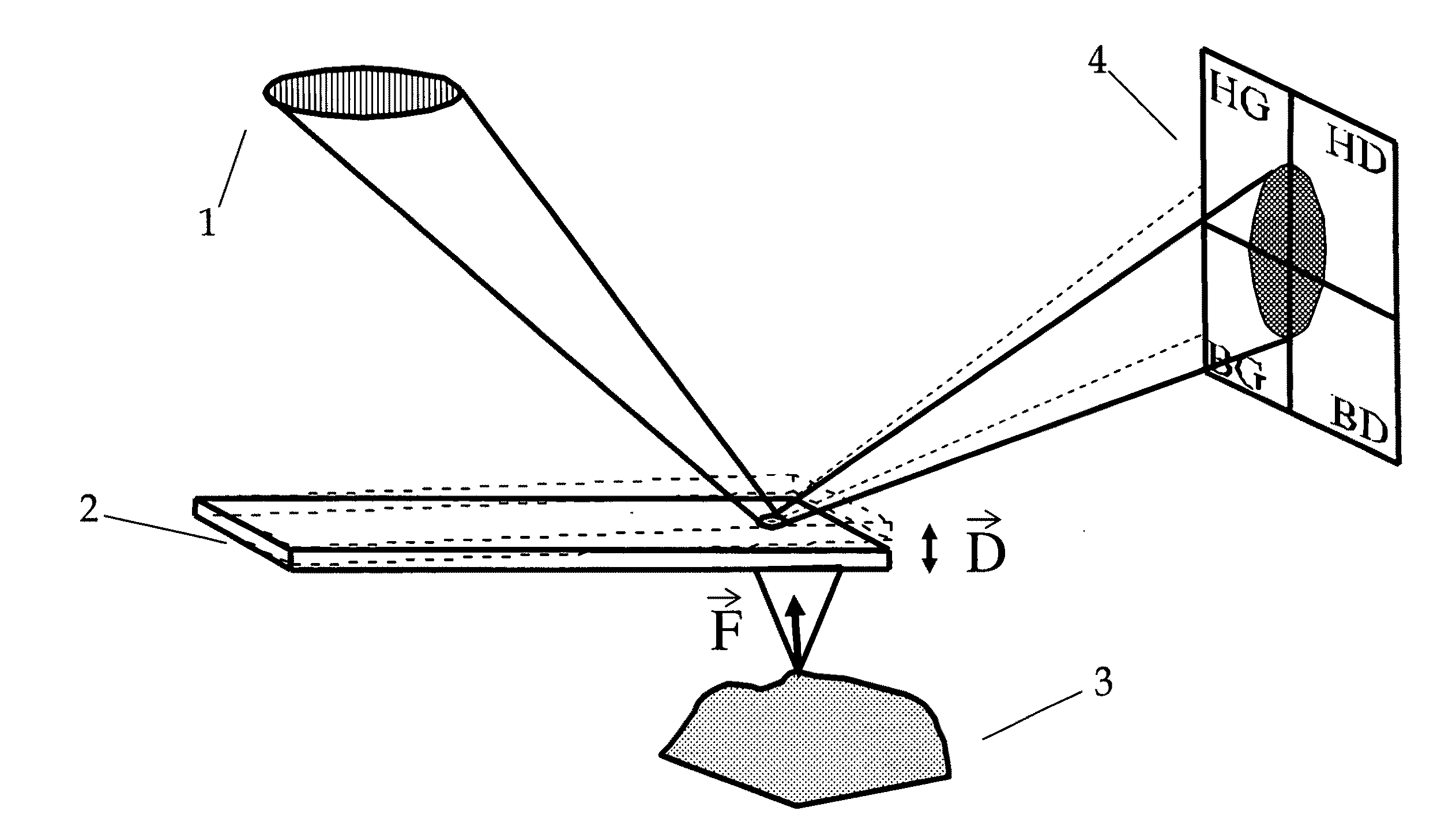
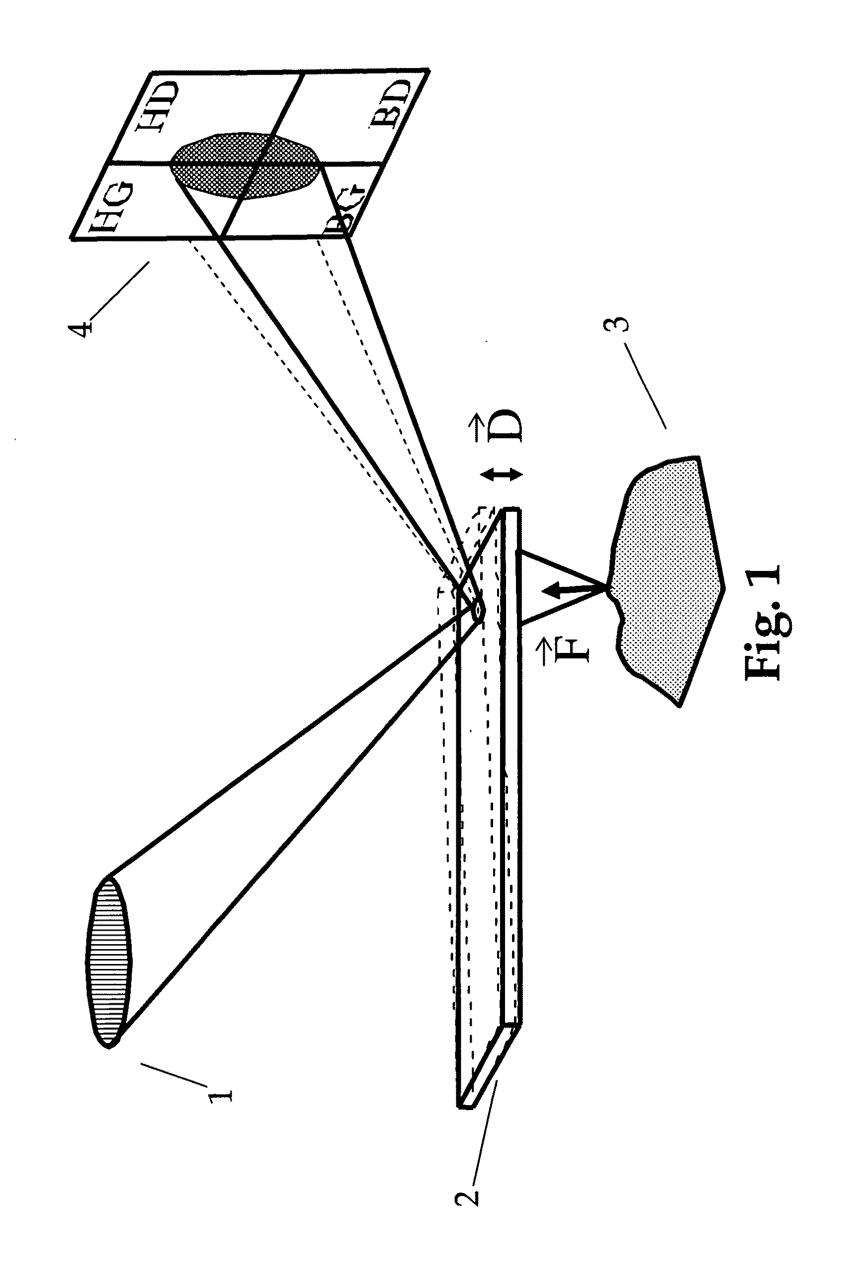
[0015]In a related embodiment, the invention is a method of measuring a localized IR spectra of a sample which includes the steps of; illuminating the sample surface with a benchtop IR source that is tunable over a wavelength range overlapping the IR fingerprint region. Light from the IR source is focused on a region and pulsed periodically at rates in excess of 100 Hz. The sample in turn absorbs IR radiation from the pulse. The absorbed energy from the pulse raises the temperature of the sample and causes a resulting pulse of thermal expansion. An AFM cantilever or equivalent probe is placed at a point on the illuminated surface, collecting data from the probe due to the absorbed radiation. The data collected may be related to probe temperature, deflection, and / or resonant oscillation of the probe in response to the IR radiation absorbed by the sample. The invention further includes methods of discriminating and / or identifying materials on the basis of IR absorption of localized regions of a sample. It also includes methods of minimizing impacts from background IR absorption by regions not directly under the probe tip.
[0019]In various embodiments, the system is designed to be easy to operate, with self-aligned, automated alignment and / or simplified alignment of the IR light source and the AFM probe on a desired region of interest of a sample. In this easy-to-use instrument, the IR source emission wavelength is computer controlled over a wide wavelength range, enabling rapid and automated scanning of a substantial fraction of the IR fingerprint region without user intervention.
[0020]In various embodiments, the invention also can automatically select appropriate modes of oscillation that are most sensitive to the motion of the sample induced by IR radiation of a region under the AFM tip. The invention can also suppress sources of background absorption that may otherwise compromise the measurement. The invention can also normalize the cantilever signals such that they diminish the impact of instrumental bias and thermomechanical properties of the sample other than IR absorption properties. As a result, the current invention can regenerate IR spectra that better match absorption spectra taken on conventional optical instruments. This process enables better matching of spectra to those existing in materials databases for accurate material identification.

Problems solved by technology

It overcomes the key limitations of the prior art which provided either very narrow band spectra or required expensive and rare facilities like the Free Electron Laser, or had insufficient optical power density and / or modulation rates.

Method used


Image

  • High frequency deflection measurement of IR absorption
  • High frequency deflection measurement of IR absorption
  • High frequency deflection measurement of IR absorption

Examples


Embodiment Construction

Photo Thermal Induced Resonance (PTIR) Overview

[0050]Referring to FIG. 3, infrared radiation 9 is incident on a region of a sample 3. At a wavelength absorbed by the sample, the absorption will typically cause a local increase in temperature and a rapid thermal expansion of the sample 3. Probe 2, is arranged to interact with the sample and transducer a signal related to the IR energy in the region under the probe tip. By “interact” we mean to position the probe tip close enough to the sample such that a probe response can be detected in response to absorption of IR radiation. For example the interaction can be contact mode, intermittent contact or non-contact mode. An associated detector can be used to read one or more probe responses to the absorbed radiation. For example the induced probe response may be a probe deflection, a resonant oscillation of the probe, and / or a thermal response of the probe (e.g. temperature change). For probe deflection and / or resonant oscillation of the ...


PUM


Abstract

An AFM based technique has been demonstrated for performing highly localized IR spectroscopy on a sample surface. Such a technique implemented in a commercially viable analytical instrument would be extremely useful. Various aspects of the experimental set-up have to be changed to create a commercial version. The invention addresses many of these issues thereby producing a version of the analytical technique that cab be made generally available to the scientific community.

Description

RELATED APPLICATIONS[0001]This application is a Continuation-in-Part of U.S. application Ser. No. 11 / 803,421, filed May 15, 2007FEDERALLY SPONSORED RESEARCH[0002]This invention was made with United States Government support under ATP Award 70NANB7H7025 awarded by the National Institute of Standards and Technology (NIST). The United States Government has certain rights in the invention.SEQUENCE LISTING[0003]Not ApplicableBACKGROUND OF THE INVENTION[0004]This invention is related to highly localized Infrared (IR) spectra on a sample surface utilizing an Atomic Force Microscope (AFM) and a variable wavelength pulsed IR source.[0005]IR spectroscopy is a useful tool in many analytical fields such as polymer science and biology. Conventional IR spectroscopy and microscopy, however, have resolution on the scale of many microns, limited by optical diffraction. It would be particularly useful to perform IR spectroscopy on a highly localized scale, on the order of biological organelles or sma...

Claims


Application Information

Patent Timeline
Patent Type & Authority Applications(United States)
IPC IPC(8): G12B21/08G01J3/42G01Q60/24
CPCB82Y35/00G01N21/3563G01Q60/32G01Q30/02
Inventor DAZZI, A. DAZZIVODOPYANOV, KONSTANTINPOLICAR, CLOTILDEREADING, MIKEKJOLLER, KEVINPRATER, CRAIG
Owner BRUKER NANO INC
Learn More