HVAC and Battery Thermal Management for a Vehicle

a battery pack and thermal management technology, applied in the direction of heat measurement, instruments, domestic cooling apparatus, etc., can solve the problems of limited battery cooling capacity, low heat rejection, low heat transfer coefficient, etc., and achieve the effect of maximizing the battery li

Inactive Publication Date: 2009-10-08
GM GLOBAL TECH OPERATIONS LLC
View PDF4 Cites 121 Cited by
  • Summary
  • Abstract
  • Description
  • Claims
  • Application Information

AI Technical Summary

Benefits of technology

[0007]An advantage of an embodiment is that the vehicle HVAC system will meet varying passenger cabin air conditioning loads while also being able to meet varying battery cooling and warming loads. The use of a coolant routing valve, chiller and battery radiator allows for added HVAC and battery thermal operating states to meet the varying passenger cabin and battery thermal loads. By maintaining the desired temperature within the battery pack, this may maximize the battery life.

Problems solved by technology

But these systems suffer from drawbacks such as low heat rejection due to the low heat transfer coefficient of air, interior passenger cabin noise, vibration and harshness (NVH) due to battery blower motor and air rush noise, limited battery cooling capacity after the vehicle has been parked in the sun (due to high air temperatures in the passenger cabin at the beginning of the drive cycle), and difficulty in ensuring that an air inlet grille between the passenger cabin and the battery thermal system does not get accidentally blocked by vehicle passengers (resulting in reduced or no battery air cooling flow).

Method used


Image

  • HVAC and Battery Thermal Management for a Vehicle
  • HVAC and Battery Thermal Management for a Vehicle
  • HVAC and Battery Thermal Management for a Vehicle

Examples


Embodiment Construction

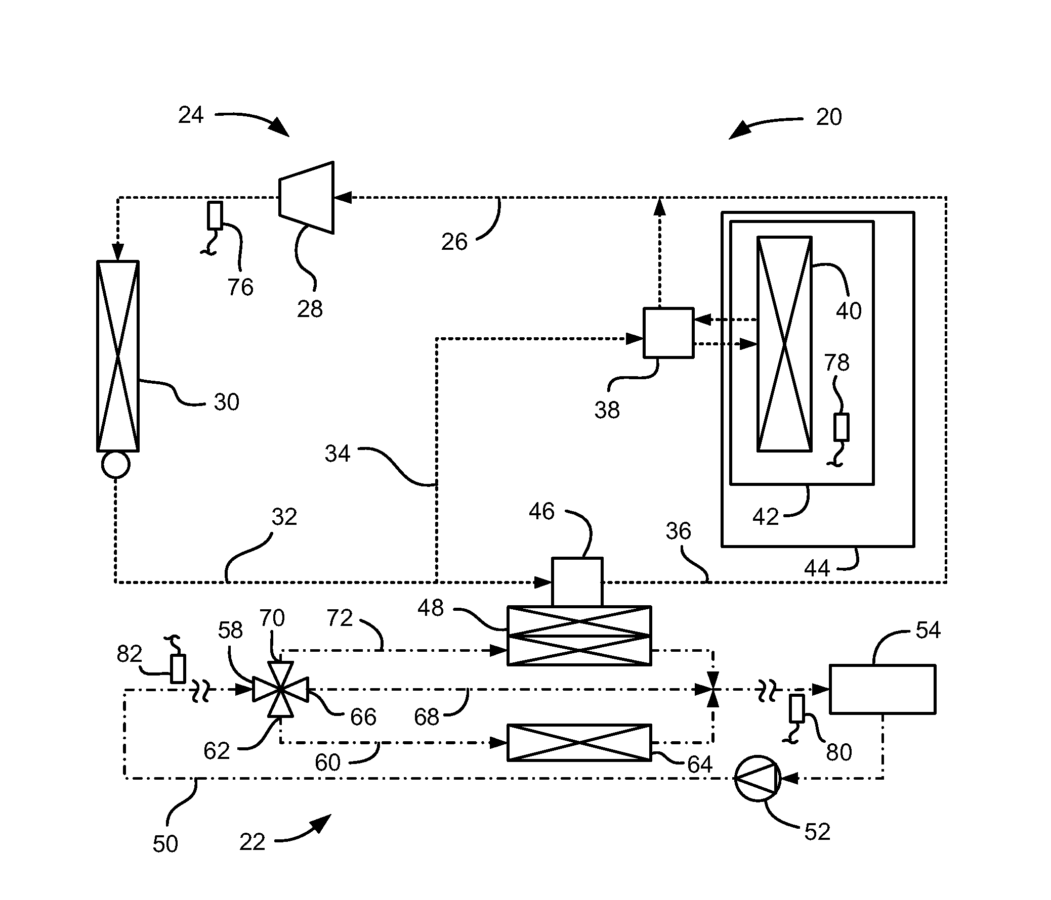
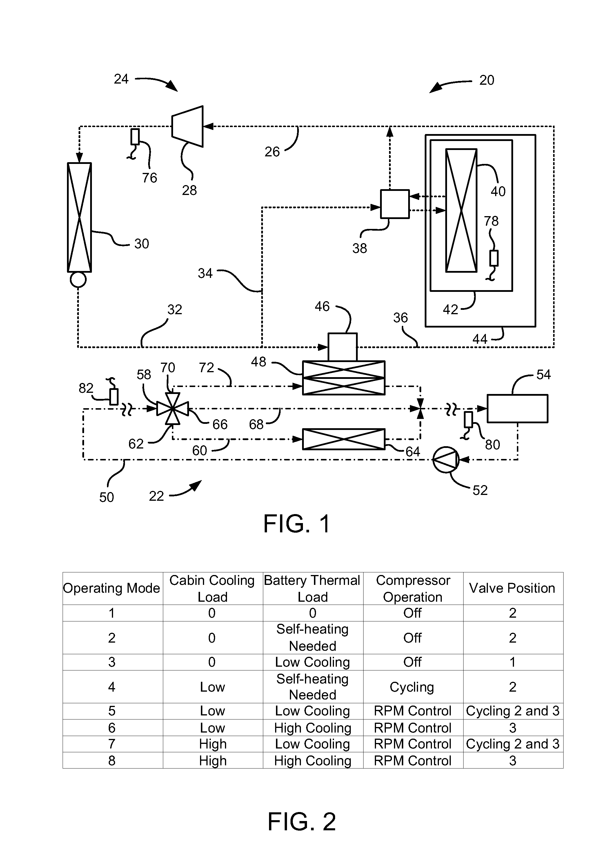
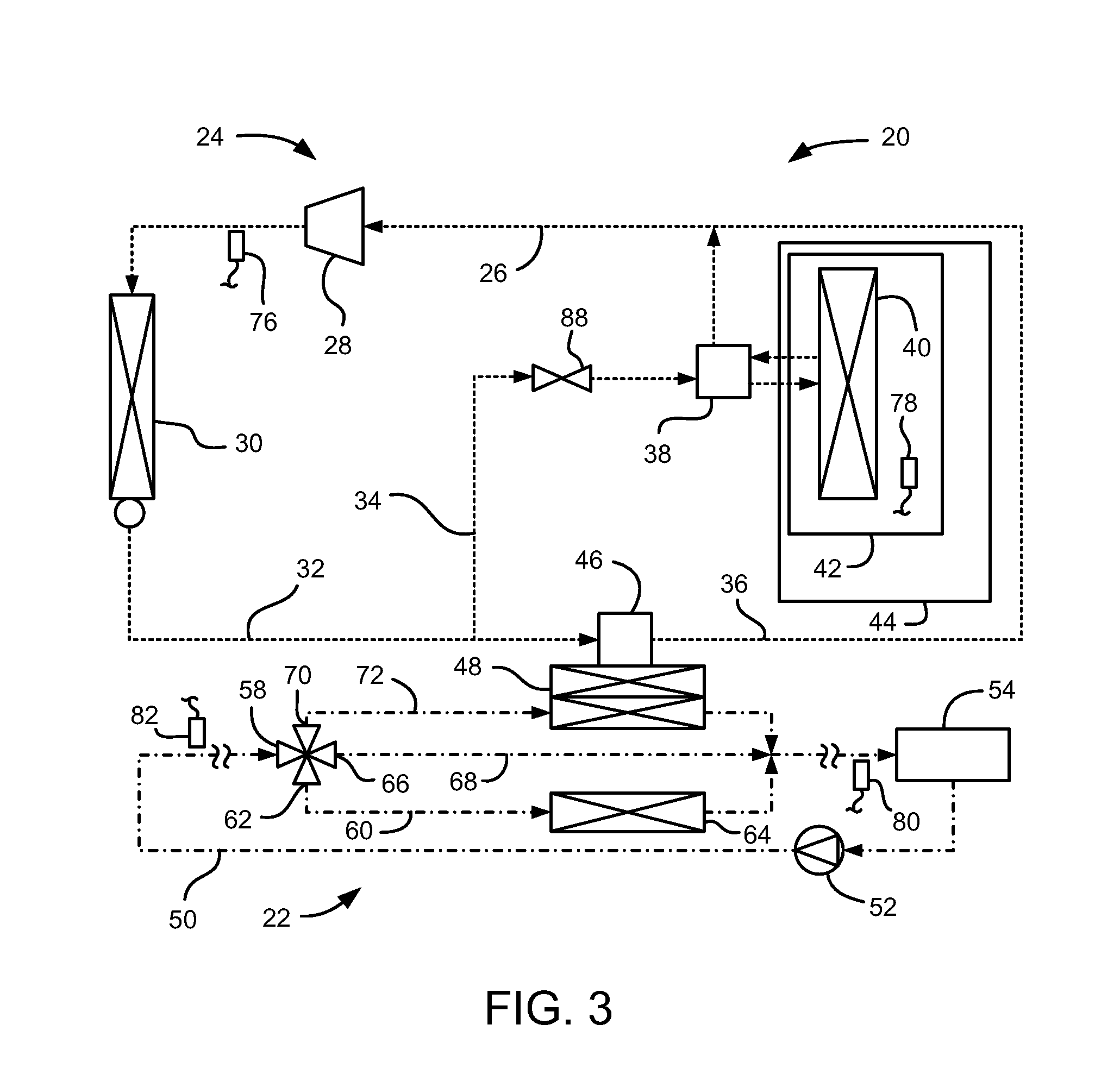
[0011]Referring to FIG. 1, a portion of a vehicle, indicated generally at 20, includes a vehicle HVAC and battery thermal system 22. The system 22 includes an air conditioning portion 24 having a refrigerant loop 26. The refrigerant loop 26 includes a refrigerant compressor 28 and a condenser 30. The refrigerant compressor 28 may be electrically driven, with an ability to adjust the speed (RPMs) of the compressor during operation. The condenser 30, in turn, directs refrigerant into a refrigerant line 32 that forks into a first leg 34 and a second leg 36 of the refrigerant loop 26.

[0012]The first leg 34 directs refrigerant through an evaporator thermal expansion valve 38 (or other expansion device) into an evaporator 40, which is located in a heating, ventilation and air conditioning (HVAC) module 42 in a passenger cabin 44 of the vehicle 20. Refrigerant exiting the evaporator 40 is directed through a return portion of the evaporator thermal expansion valve 38 and back to the compres...


PUM


Abstract

A HVAC and battery thermal system and method for a vehicle having a passenger cabin and a battery pack is disclosed. The system may comprise a refrigerant loop and a coolant loop. The refrigerant loop includes a first leg and a second leg, the first leg including an expansion device and an evaporator, and the second leg including an expansion device and a chiller. The coolant loop directs coolant through the battery pack and includes a controllable coolant routing valve, a bypass branch and a chiller branch, with the chiller in the chiller branch. The coolant routing valve has a bypass outlet that directs the coolant into the bypass branch and a chiller outlet that directs the coolant into the chiller branch. The coolant loop may also include a radiator branch and battery radiator, with the coolant routing valve including a radiator outlet that directs the coolant into the radiator branch.

Description

BACKGROUND OF INVENTION[0001]The present invention relates generally to heating, ventilation and air conditioning (HVAC) systems and thermal systems for battery packs in vehicles.[0002]Advanced automotive vehicles are being introduced that employ a battery pack to store large amounts of energy for electric propulsion systems. These vehicles may include, for example, plug-in hybrid electric vehicles, electric vehicles with an internal combustion engine that is used as a generator for battery charging, and fuel cell vehicles. In general, these battery packs require some type of thermal system for cooling and warming the battery pack.[0003]Typical battery thermal systems used to cool and warm the battery pack rely on air flow from the vehicle HVAC system. This may be passenger cabin air that is directed through the battery pack. But these systems suffer from drawbacks such as low heat rejection due to the low heat transfer coefficient of air, interior passenger cabin noise, vibration a...

Claims


Application Information

Patent Timeline
Patent Type & Authority Applications(United States)
IPC IPC(8): F25D23/12B60H1/32G01K13/02G01K13/024
CPCB60H1/00278B60H1/00885B60H2001/00307B60H2001/00949H01M10/5095H01M10/5016H01M10/5075H01M10/5077H01M10/5004H01M10/625H01M10/663H01M10/6568H01M10/6567H01M10/613Y02E60/10
Inventor NEMESH, MARK D.STANKE, EDWIN J.MARTINCHICK, MATTHEW J.IBRI, WISSAMSINGH, KUL WINDER
Owner GM GLOBAL TECH OPERATIONS LLC
Why Eureka
Try Eureka