Coiled Tubing Injector Head

a technology of injectors and tubing reels, which is applied in the field of coiled tubing injectors, can solve the problems of weight and maintenance burden, inadequacies of tubing reels as winch drums, and considerable prior art concerning only the details of chain loops

Active Publication Date: 2009-10-08
ASEP HLDG
View PDF17 Cites 24 Cited by
  • Summary
  • Abstract
  • Description
  • Claims
  • Application Information

AI Technical Summary

Benefits of technology

[0015]Each link may comprise side members and a cross member extending therebetween, and one or more shafts extending between the side members. One or more rollers may be mounted on the shafts between the side members. The gripper blocks may be provided on the cross members. The gripper blocks may be formed integrally or otherwise non-releasably fixed to the cross members, though in certain embodiments the gripper blocks may be releasably mounted to the cr

Problems solved by technology

The tubing reel is not appropriate as a winch drum, since the stresses involved in using it so would destroy the tubing.
Furthermore, considerable prior art exists concerning only the details of the chain loops.
Roller chain is inexpensive, readily available and very strong, yet its incorporation into the chain loop assemblies results in a weight and maintenance burden, since the prior art assemblies all comprise the many elements of two heavy duty roller chains, plus the gripper blocks which contact the tubing and sometimes their separable carriers 11 too.
However, there also exist a number of disadvantages, namely the requirement for bulky drive hoses, mechanical inefficiency leading to heat dissipation problems and limited control flexibility, especially at low constant speeds.
The gripping fo

Method used


Image

  • Coiled Tubing Injector Head
  • Coiled Tubing Injector Head
  • Coiled Tubing Injector Head

Examples


Embodiment Construction

[0030]The present embodiments as illustrated and described herein represent currently the best ways known to the applicant of putting the invention into practice, but they are not the only ways by which the invention could be achieved. Thus, the various embodiments are illustrated and will be described only by way of example.

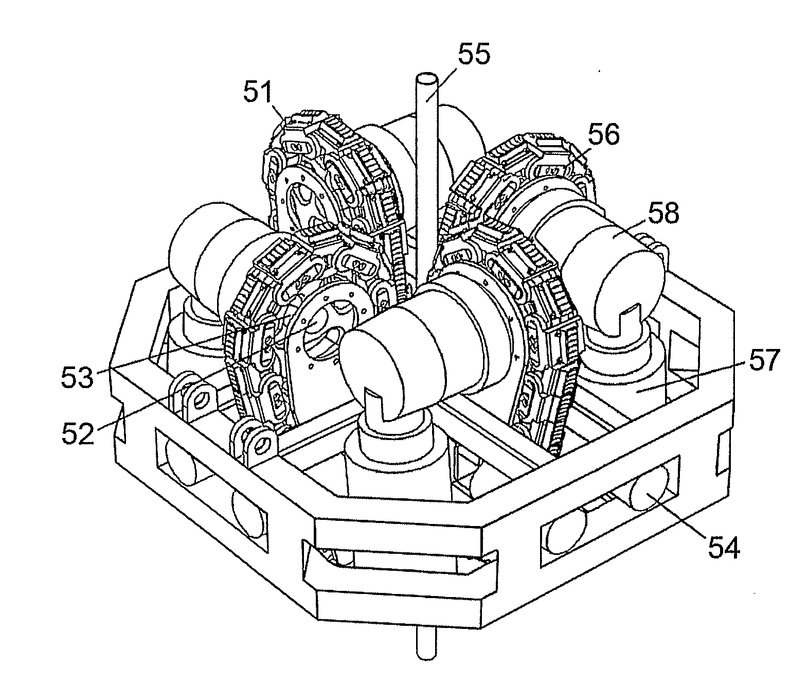
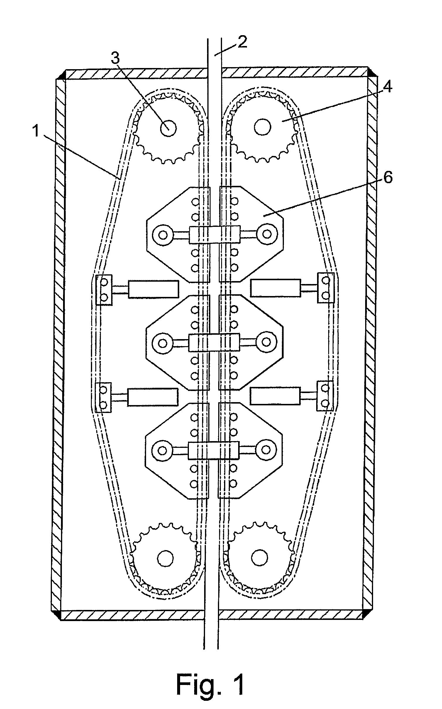
[0031]The invention relates to an improved coiled tubing injector head of the general type illustrated in FIG. 1 and comprising a plurality of endless or closed chain loops 1, each having one practically straight side adjacent to the other chain loops and biased against a tubing 2 running between all loops. The biasing arrangement, for example a hydraulically linked roller assembly 6, acts so as to grip the tubing and allow its transit into and out of a well by motion of the chains.

[0032]In the first embodiment of the invention, as illustrated in FIG. 6, the chain of the loop is composed of two link types 23, 24 cooperatively configured to form a chain structure...


PUM


Abstract

An improved coiled tubing injector head, comprising a plurality of powered chain loops (1), each having one practically straight side adjacent to the other chain loop(s) and biased against a tubing (2) running in-between all the loops so as to grip the tubing and allow its transit into and out of a well. The chain loops are assembled from multifunctional links (23, 24) which both transmit drive and also form carriers for replaceable gripper blocks or are the carriers and gripper blocks combined, without need of a roller link chain or chains in addition to the multifunctional links. Three or more chain loops are provided, and the chain loops are driven by electric motors.

Description

FIELD OF THE INVENTION[0001]The invention relates generally to coiled tubing injectors for handling continuous or coiled tubing for insertion into and retrieval from a wellbore with intention to rectify or enhance the wellbore by hydraulic or mechanical means.BACKGROUND TO THE INVENTION[0002]Coiled tubing well intervention has been known in the oil production industry for many years. A great length, often exceeding 15,000 ft, of small diameter, typically 1.5 in, steel tubing is handled by coiling on a large reel, which explains the name of coiled tubing. The tubing reel is not appropriate as a winch drum, since the stresses involved in using it so would destroy the tubing. The accepted solution in the industry is to pull tubing from the reel, as it is required and pass the tubing around a curved guide arch, or ‘gooseneck’, so that it lies on a common vertical axis with the wellbore. To control passage of tubing into and out of the wellbore, a device called a coiled tubing injector h...

Claims


Application Information

Patent Timeline
IPC IPC(8): E21B19/22
CPCE21B19/22
Inventor KOOPMANS, SIETSE JELLEHUIZER, ALDO
Owner ASEP HLDG
Why Eureka
Try Eureka