Mould and method for vacuum assisted resin transfer moulding

a technology of vacuum assisted resin and transfer moulding, which is applied in the direction of drawing profiling tools, machines/engines, and final product manufacture, etc., can solve the problem of adding weight without providing a substantial structural benefi

Active Publication Date: 2009-10-08
SIEMENS GAMESA RENEWABLE ENERGY AS
View PDF20 Cites 31 Cited by
  • Summary
  • Abstract
  • Description
  • Claims
  • Application Information

AI Technical Summary

Benefits of technology

[0008]It is therefore a first objective of the present invention to provide an advantageous means for producing fibre reinforced laminated structures. It is a second objective of the present invention to provide an advantageous method for vacuum assisted resin transfer moulding of a fibre reinforced laminated structure

Problems solved by technology

If the resin distribution system, i.e. the inlet pipes and / or the resin distribution layer, remains in the laminated structure, it adds to weight without providing a substantial structural benefit.

Method used


Image

  • Mould and method for vacuum assisted resin transfer moulding
  • Mould and method for vacuum assisted resin transfer moulding
  • Mould and method for vacuum assisted resin transfer moulding

Examples


first embodiment

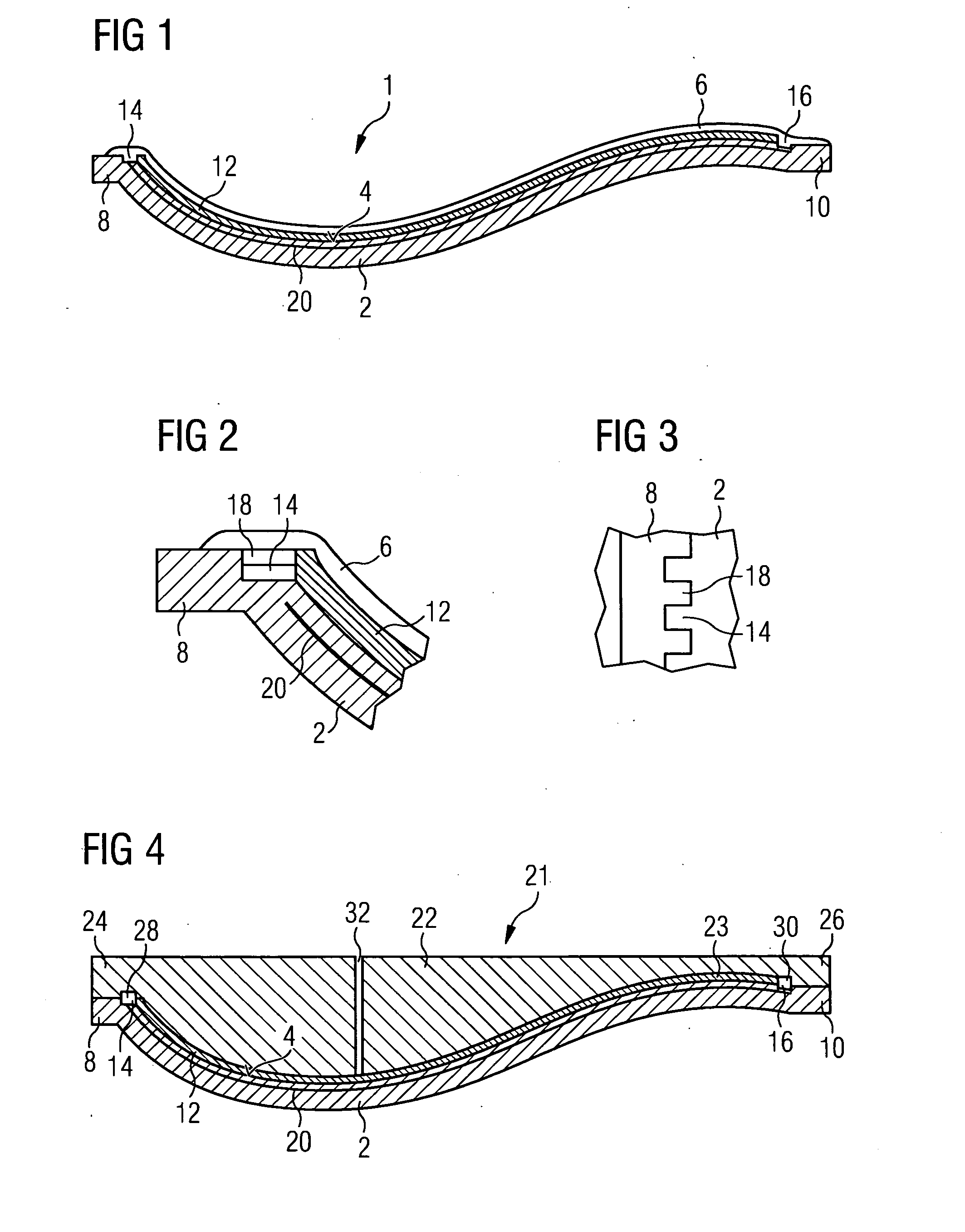
[0025]the inventive mould is shown in FIG. 1. The figure shows a mould for a shell part of a fibre reinforced laminate wind turbine rotor blade. The shell part to be formed by the mould forms the pressure side of the later rotor blade, i.e. the side which shows substantially towards the direction from which the wind comes during operation of the wind turbine. A similar mould (not shown) will be used for forming the suction side shell part. The wind turbine rotor blade is then formed by joining the pressure side shell and the suction side shell by glue joints.

[0026]The mould 1 shown in FIG. 1 comprises a first mould part 2 which is made from a rigid and structurally stable material. The mould part 2 comprises an inner surface 4 which defines a negative impression of the wind turbine rotor blade's pressure side shell part. The surface 4 of the mould part 2 may be provided with a suitable release agent which allows for removing the pressure side shell part from the mould after the moul...

third embodiment

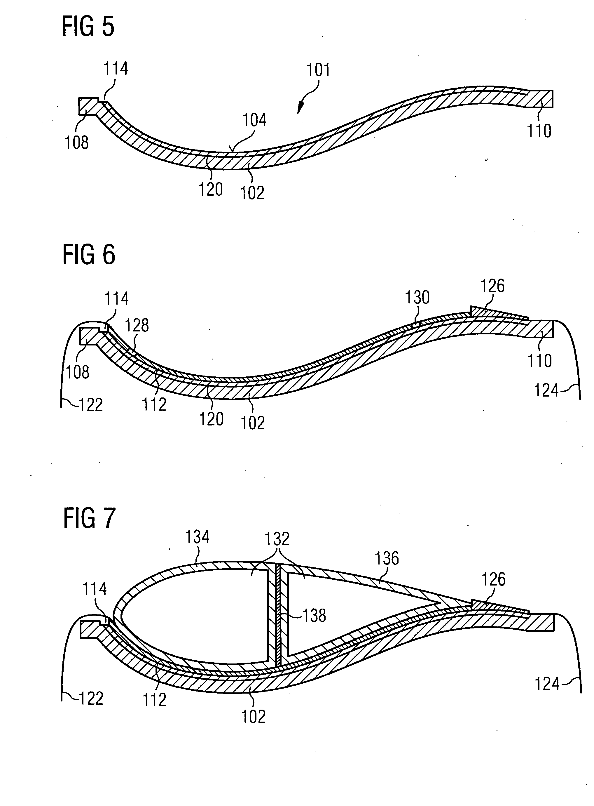
[0036]the inventive mould and its use will be described with respect to FIGS. 5 to 9.

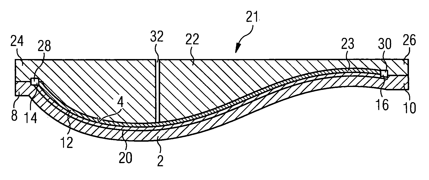
[0037]FIG. 5 shows a first mould part of the mould 101 according to the third embodiment which corresponds to the first mould parts of the first and second embodiments except for the fact that no recess 16 is present in the mould part's edge 110 that is located where the wind turbine rotor blade's trailing edge will be formed. The remaining parts of the first mould part 102 of the third embodiment correspond to the respective parts of the mould part 2 of the first and second embodiments and will therefore not be described again. Elements of the mould part 102 which correspond to the mould part 2 are designated with the reference numerals which are increased by 100 with respect to those used for the mould part 2.

[0038]A layer stack 112 is formed in the first mould part 102 (see FIG. 6) by first putting one or more layers of fibre reinforcement material in the mould, then putting a core material atop ...


PUM

PropertyMeasurementUnit
structurally stableaaaaaaaaaa
outer dimensionsaaaaaaaaaa
dimensionsaaaaaaaaaa

Abstract

A mould and method for vacuum assisted resin transfer moulding of a fibre reinforced laminated structure are provided. The mould includes a first mould part and a second mould part. The first mould part defines a negative impression of the laminated structure, being structurally stable and forming a support for fibre reinforcement layers of the laminated structure. The second mould part connectable to the first mould part for closing the mould and defines together with the first mould part an enclosed space which can be evacuated. The mould further includes a flow duct for guiding a liquid polymer which is formed as a recess in the first mould part and/or a recess in the second mould part that is open towards the enclosed space and extends along a section of the periphery of the first mould part and/or the second mould part.

Description

CROSS REFERENCE TO RELATED APPLICATIONS[0001]This application claims priority of European Patent Office application No. 08006813.3 EP filed Apr. 3, 2008, which is incorporated by reference herein in its entirety.FIELD OF INVENTION[0002]The present invention relates to a mould for a vacuum assisted resin transfer moulding of a fibre laminated structure, in particular of a wind turbine rotor blade, and to a method for vacuum assisted resin transfer moulding.BACKGROUND OF INVENTION[0003]Vacuum assisted resin transfer moulding (VARTM) of large structures has to date involved in the inclusion of conduits for resin distribution into the moulded structure. Examples therefore are disclosed in EP 1 310 351 B1, WO 2006 / 058540 A1, WO 2006 / 058541 A1, and WO 2007 / 038930 A1.[0004]EP 1 310 351 B1 describes a mould for wind turbine rotor blades which comprises a lower mould part, an upper mould part, and a core. For forming a laminated rotor blade, fibre reinforcement layers are layered in the lowe...

Claims


Application Information

Patent Timeline
Patent Type & Authority Applications(United States)
IPC IPC(8): B29C70/36B29C70/28B29D99/00
CPCB29C33/0061B29C70/443B29C70/48Y02E10/721B29L2031/08B29L2031/085F03D1/0675B29C70/548Y02E10/72Y02P70/50
Inventor BURCHARDT, CLAUSHURUP, ALLANNORLEM, MICHAELOLESEN, BENDTSTIESDAL, HENRIK
Owner SIEMENS GAMESA RENEWABLE ENERGY AS
Why Eureka
Try Eureka