
Stage unit, exposure apparatus, and device manufacturing method

Inactive Publication Date: 2009-10-08
CANON KK
View PDF9 Cites 29 Cited by
  • Summary
  • Abstract
  • Description
  • Claims
  • Application Information

AI Technical Summary

Benefits of technology

[0022]The present invention provides a positioning stage unit capable of achieving the swapping operation for interchanging a plurality of stages with a simple structure without increasing the number of current amplifiers.

Problems solved by technology

Disadvantageously, the necessity of the many current amplifiers results in an increase in cost and further results in an increase in footprint of an electrical component rack.

Method used


Image

  • Stage unit, exposure apparatus, and device manufacturing method
  • Stage unit, exposure apparatus, and device manufacturing method
  • Stage unit, exposure apparatus, and device manufacturing method

Examples


first embodiment

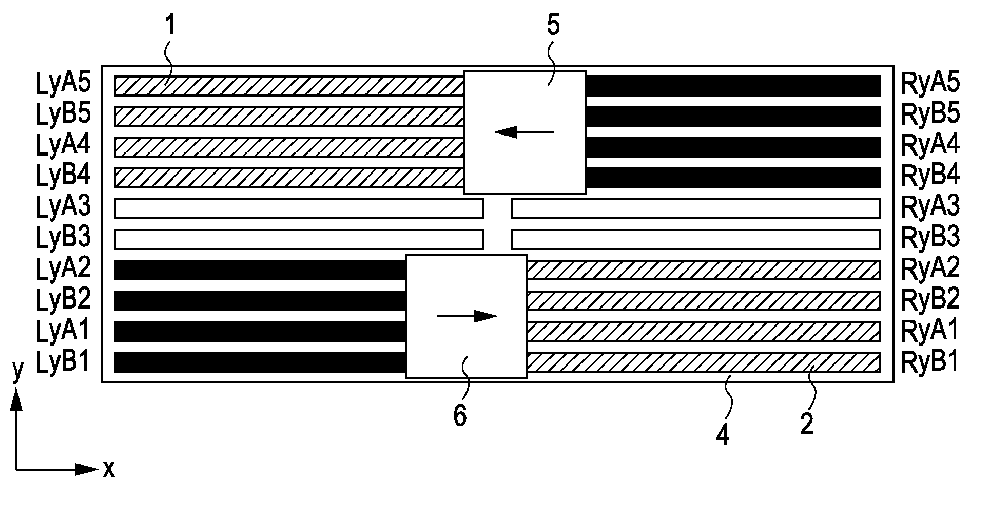
[0041]The structure of a twin stage unit including a planar motor in accordance with the present invention is the same as that shown in FIGS. 10A to 10C. The stage unit includes a first coil array 1 in which first coils extending in the x direction are arranged in the y direction perpendicular to the x direction and a second coil array 2 in which second coils extending in the x direction are arranged in the y direction. The two coil arrays are disposed adjacent to each other in the x direction.

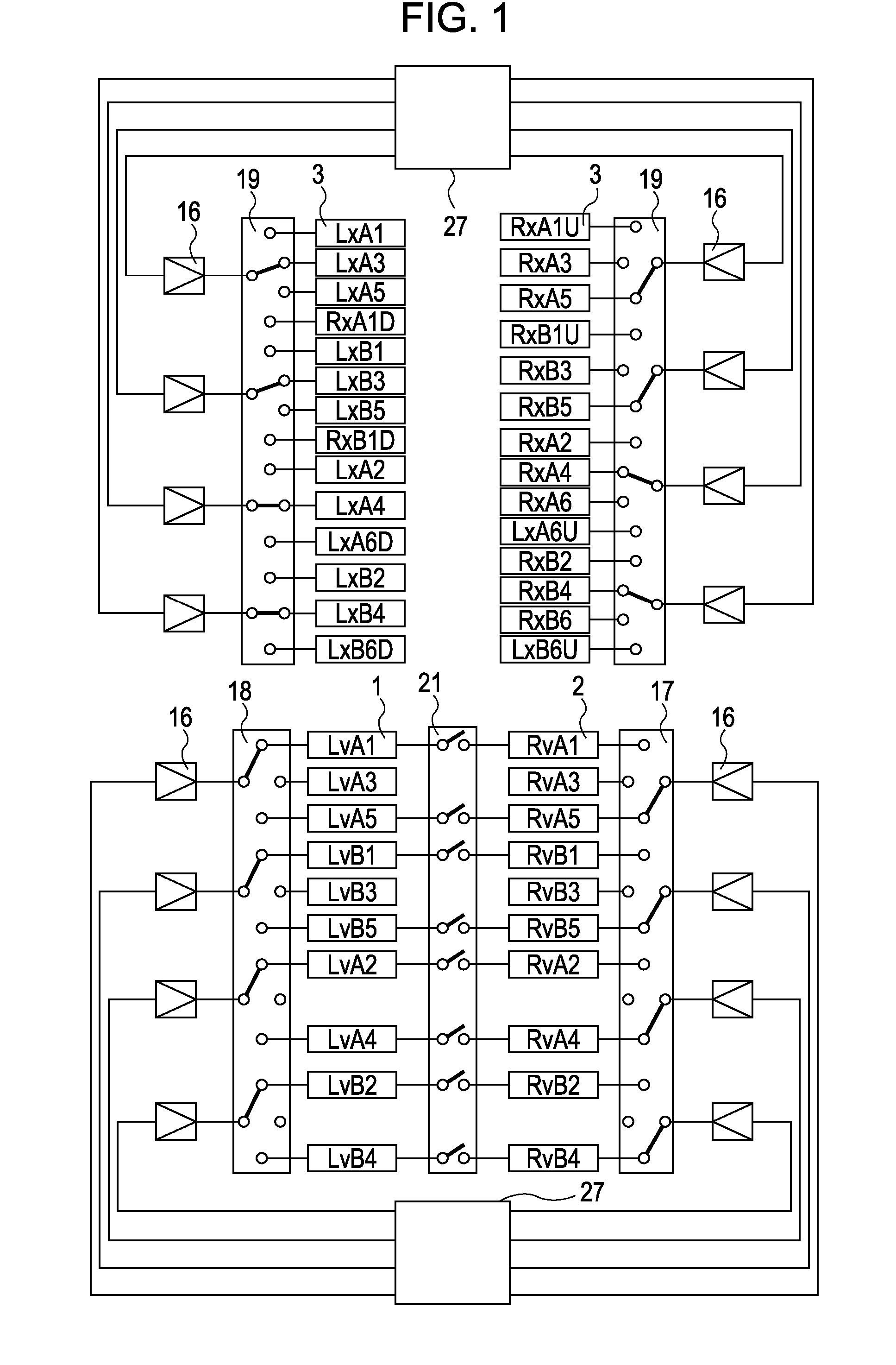
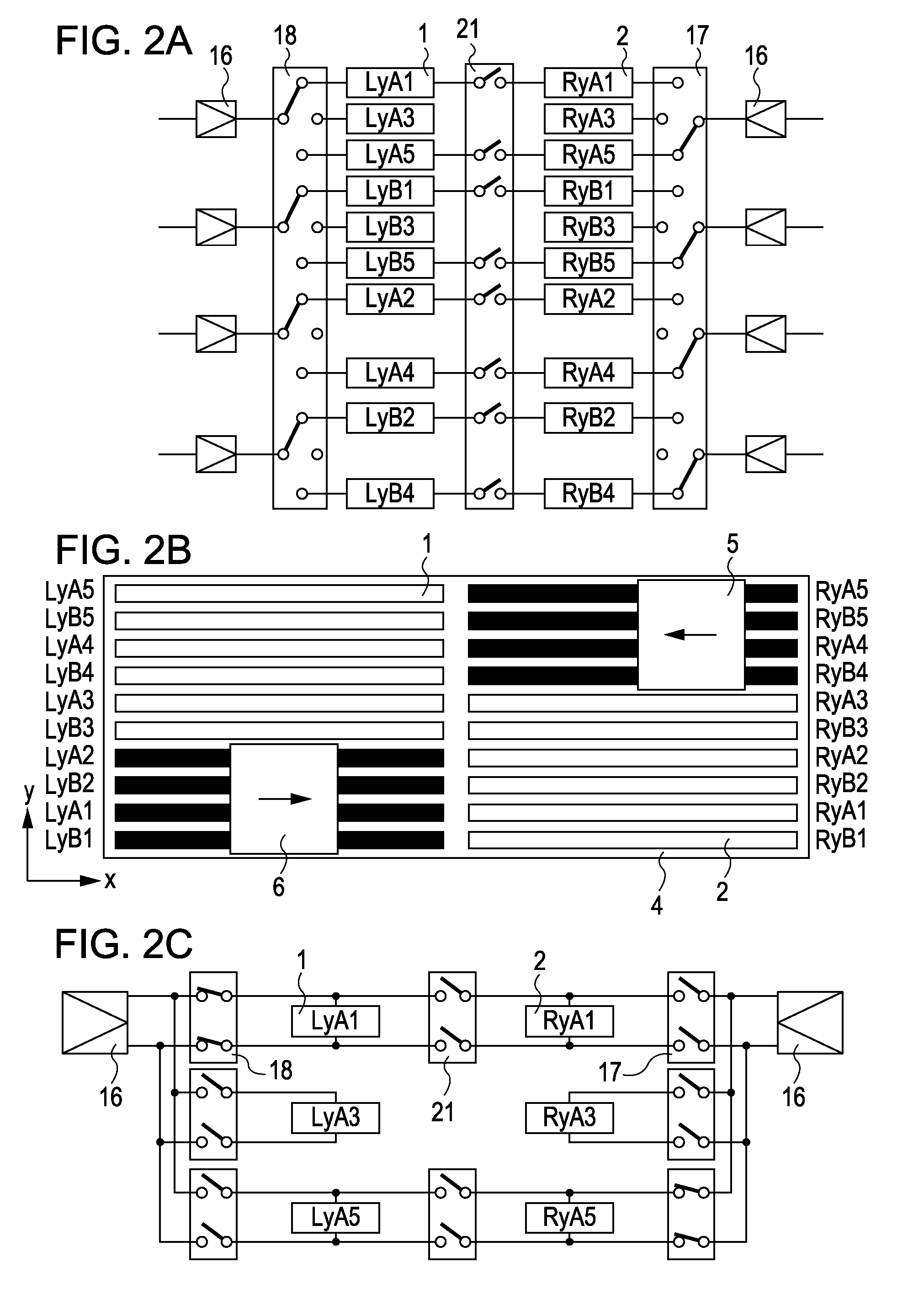
[0042]In addition, a third coil array 3 in which third coils extending in the y direction are arranged in the x direction is placed within a stator 4 such that the third coil array 3 covers the first coil array 1 and the second coil array 2 as shown in FIG. 10C. To describe an operation for switching between the coils, reference symbols, e.g., LxA1, RyA5, and other similar symbols are assigned to the respective coils as shown in the figures.

[0043]FIG. 1 illustrates a coil switching circuit in ...

second embodiment

[0056]Referring to FIG. 6A, a stage unit according to the present invention includes a first coil array 1 in which first coils extending in the y direction are arranged in the x direction and a second coil array 2 in which second coils extending in the y direction are arranged in the x direction. The two coil arrays are disposed adjacent to each other in the y direction. In addition, a fifth coil array 32 in which fifth coils having a length in the y direction longer than the lengths of the first and second coils are arranged in the x direction is located next to the arrangement of the first coil array 1 and the second coil array 2 in the x direction.

[0057]As shown in FIGS. 6B and 6C, a third coil array 3 in which third coils extending in the x direction are arranged in the y direction is placed within a stator 4 such that the third coil array 3 underlies the first coil array 1 and the second coil array 2. In addition, a sixth coil array 42 in which sixth coils extending in the x di...


PUM


Abstract

A stage unit includes the following elements. A stator includes a first coil array in which first coils extending in the x direction are arranged in the y direction, a second coil array in which second coils extending in the x direction are arranged in the y direction and which is located next to the first coil array in the x direction, and a third coil array in which third coils extending in the y direction are arranged in the x direction and which covers the first and second coil arrays. A movable member moves above the stator. A controller controls driving of the movable member by allowing current amplifiers to supply current to the coils included in the first, second, and third coil arrays. A switch is capable of connecting the first coil to the second coil.

Description

BACKGROUND OF THE INVENTION[0001]1. Field of the Invention[0002]The present invention relates to stage units for positioning an object, and in particular, relates to a stage unit suitable to position a substrate or an original in a manufacturing apparatus, e.g., an exposure apparatus, for manufacturing a device, such as a semiconductor device or a liquid crystal device.[0003]2. Description of the Related Art[0004]As for stage units, used in exposure apparatuses, requiring high-accuracy positioning, a stage unit including a planar motor has attracted attention. Regarding wafer stages, attention has focused on a twin stage structure in which two movable stages are provided. An exposure operation for exposing a wafer to form a pattern on the wafer is performed simultaneously with a measurement operation for measuring the position of a previously formed pattern, so that an increase in throughput can be expected. Japanese Patent Laid-Open No. 2005-253179 discloses a stage unit including ...

Claims


Application Information

Patent Timeline
IPC IPC(8): G03B27/58H02K41/03G05B11/01H01L21/683
CPCG03B27/58H02K41/03G03F7/70758G03F7/70725H02K2201/18
Inventor OHISHI, SHINJI
Owner CANON KK
Learn More