Radio-Access Method for Mobile-Radio Networks, Related Networks and Computer Program Product

a mobile radio and access method technology, applied in the direction of wireless communication services, electrical equipment, wireless communication services, etc., can solve the problems of signal overload on the uplink and downlink, processing delays are inevitable, and call drop, etc., to achieve the effect of degree of flexibility

Inactive Publication Date: 2009-10-08
TELECOM ITALIA SPA
View PDF15 Cites 96 Cited by
  • Summary
  • Abstract
  • Description
  • Claims
  • Application Information

AI Technical Summary

Benefits of technology

[0022]may exploit the information linked to the mobility of the user, to the load of the cells, to the characteristics of the service requested by the user, this enabling a degree of flexibility typically associated to hierarchical structures.

Problems solved by technology

A technical problem associated to the widespread use of microcells is linked to the service supplied to high-mobility users.
A user who is moving at high speed in a microcell context, in fact, executes a very large number of handover procedures between the cells, which cause a signalling overload both on the uplink and on the downlink.
In addition to the signalling overload, it should be recalled that processing delays are inevitably associated to the operations of measurement and to the consequent operations for support of mobility.
In the case of small cell dimensions these processing delays can prove critical for execution of handoff procedures, with consequent possible drop of the call.
As highlighted in: T. Ojampera, R. Prasad, “Wideband CDMA for Third Generation Mobile Communications”, Artech House, 1998, pages 252-253, the use of a system with macrocells and microcells on the same W-CDMA carrier presents numerous problems of design and operation.
This condition can be caused, for example, by a delay in the handover procedures, as mentioned above, and brings about an increase in the interference suffered by the microcell and, consequently, a deterioration in the performance for all the users served by the microcell itself.
Frequently, however, the UMTS operators have a very limited number of carriers available.
In the case where the operator has only two carriers available for example, this constraint results in an obligate choice and prevents alternative solutions such as, in particular, the use of both of the carriers at the microcell layer, which maximizes the overall capacity of the W-CDMA radio access.
Additionally, architectures of a Distributed-Antenna System (DAS) type so far known do not enable implementation of a hierarchical structure.
The opto-RF transducers, housed in canisters, are mounted on telephone or power poles to provide radio link coverage to mobile and portable phones located in a microcell area, e.g., in congested metropolitan area where space for a roof-top base station is very limited and expensive.

Method used


Image

  • Radio-Access Method for Mobile-Radio Networks, Related Networks and Computer Program Product
  • Radio-Access Method for Mobile-Radio Networks, Related Networks and Computer Program Product
  • Radio-Access Method for Mobile-Radio Networks, Related Networks and Computer Program Product

Examples


Embodiment Construction

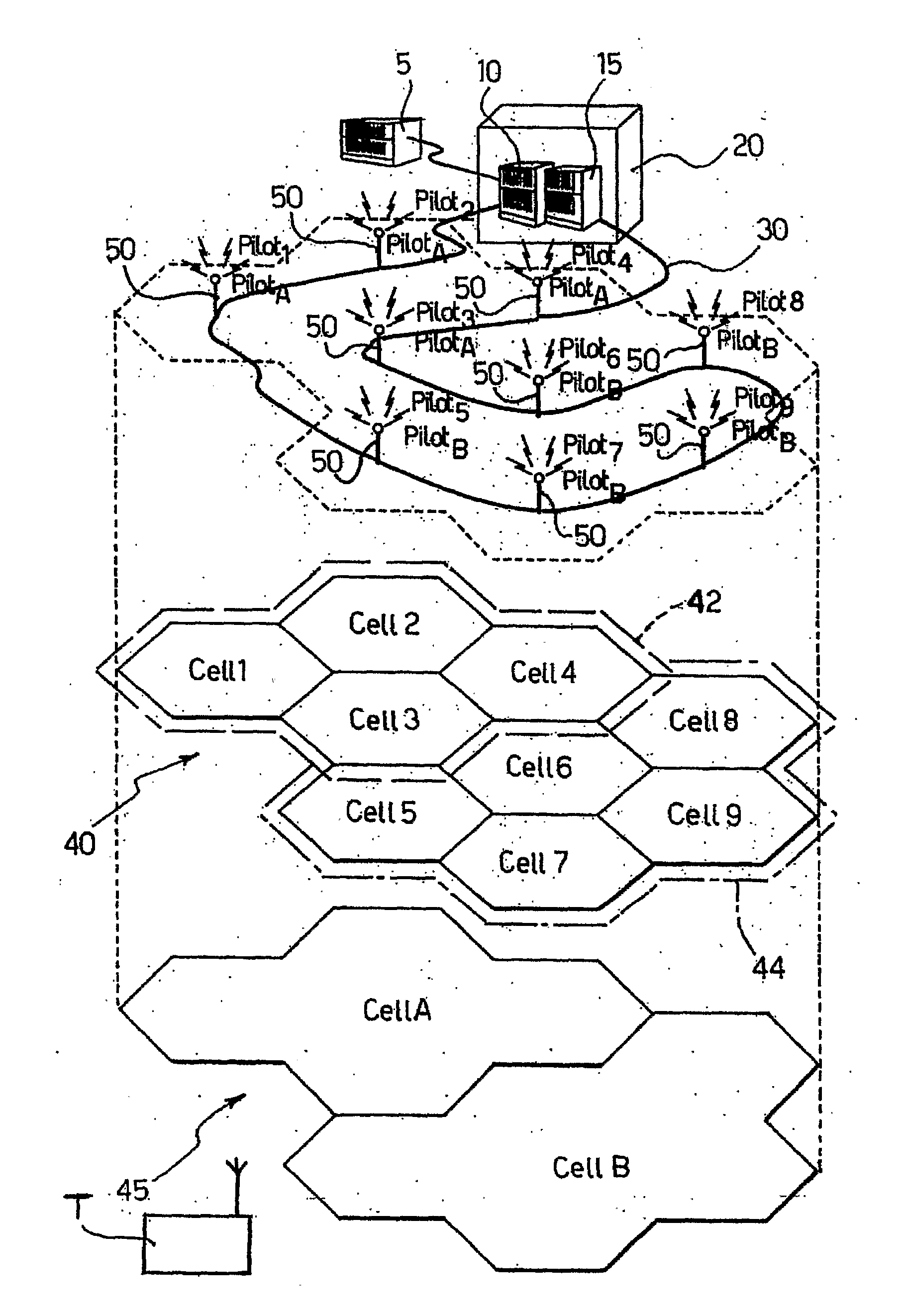
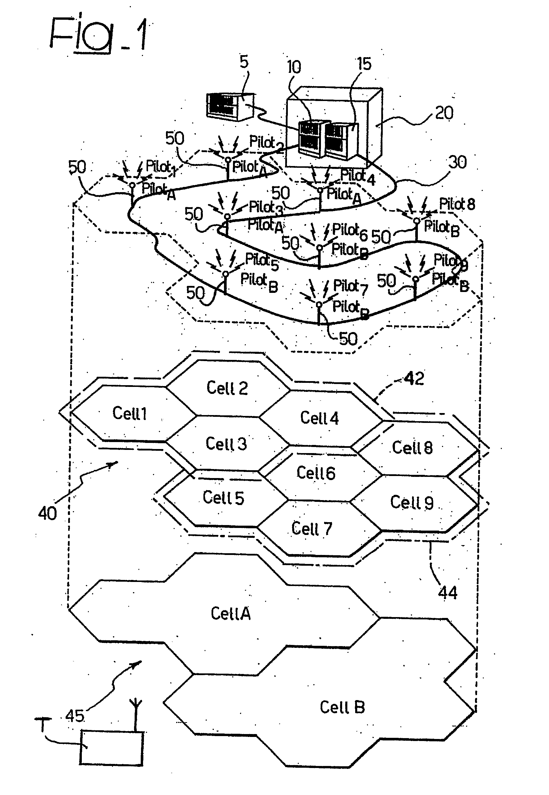
[0050]FIG. 1 illustrates an example of base structure of a distributed antenna system. Specifically, the arrangement shown in FIG. 1 can be designated a Hierarchical Distributed-Antenna System (H-DAS).

[0051]The system in question includes a network controller 5, in which there reside the modules that control operation of the hierarchical system, a set of radio base stations 10, 15 of a conventional type which, by way of non-limiting example, are represented co-allocated in a single location referred to as “Base Station Hotel” designated as a whole by the reference number 20.

[0052]As is well known, in UMTS technology, the apparatuses that perform the functions of radio base stations (BTSs) 10, 15 assume the name of Nodes B, whilst the network controller 5 assumes the name of Radio Network Controller (RNC).

[0053]The radio base stations 10, 15 are connected through a connection 30 of the Radio Over Fibre (ROF) type to a set of remotized antenna elements 50 (nine in number in the exampl...


PUM


Abstract

A mobile-radio network includes radio base stations providing radio coverage to the users of the network via antenna elements, wherein the antenna elements are equipped with at least one first communication channel and at least one second communication channel. The first communication channel provides a first layer of individual microcell radio coverage for the antenna elements. The second communication channel is made common to groups of the antenna elements and provides a second layer of virtual macrocell radio coverage, wherein the coverage of each virtual macrocell aggregates the microcell radio coverages of the antenna elements included in the respective group.

Description

FIELD OF THE INVENTION[0001]The present invention relates to techniques for radio access in mobile-radio systems.[0002]The invention has been developed with particular attention paid to its possible use in networks including distributed radio base stations.DESCRIPTION OF THE KNOWN ART[0003]The mobile-radio system must guarantee a service of communication between a fixed network and mobile terminals (user terminals) randomly distributed over a certain service area. The radio coverage is obtained by installing a plurality of radio base stations, each of which has the task of covering a certain portion of the area, referred to as a cell, whence the name of “cellular systems”. The generic mobile terminal can communicate with the fixed network through one of the radio base stations of the system, for example the one from which it receives the radio signal with best quality. The procedures through which the terminal, once turned on, chooses the radio base station from which to receive the...

Claims


Application Information

Patent Timeline
Patent Type & Authority Applications(United States)
IPC IPC(8): H04B7/216H04W40/00H04W16/32
CPCH04W16/32
Inventor LUDOVICO, MICHELEGUERRINI, CLAUDIO
Owner TELECOM ITALIA SPA
Why Eureka
Try Eureka