

Moving object trajectory estimating device
a technology for moving objects and trajectory estimation, which is applied in the direction of vehicular safety arrangements, pedestrian/occupant safety arrangements, instruments, etc., can solve the problem of not performing appropriate trajectory estimation, and achieve the effect of enhancing accuracy of trajectory estimation, estimating more accurately, and speeding up estimation processing
- Summary
- Abstract
- Description
- Claims
- Application Information
AI Technical Summary
Benefits of technology
Problems solved by technology
Method used
Image

Examples
first embodiment
[0021]A moving object trajectory estimating device 1 may be applied to a controller of an automatically driven vehicle and estimates the trajectories of other vehicles.
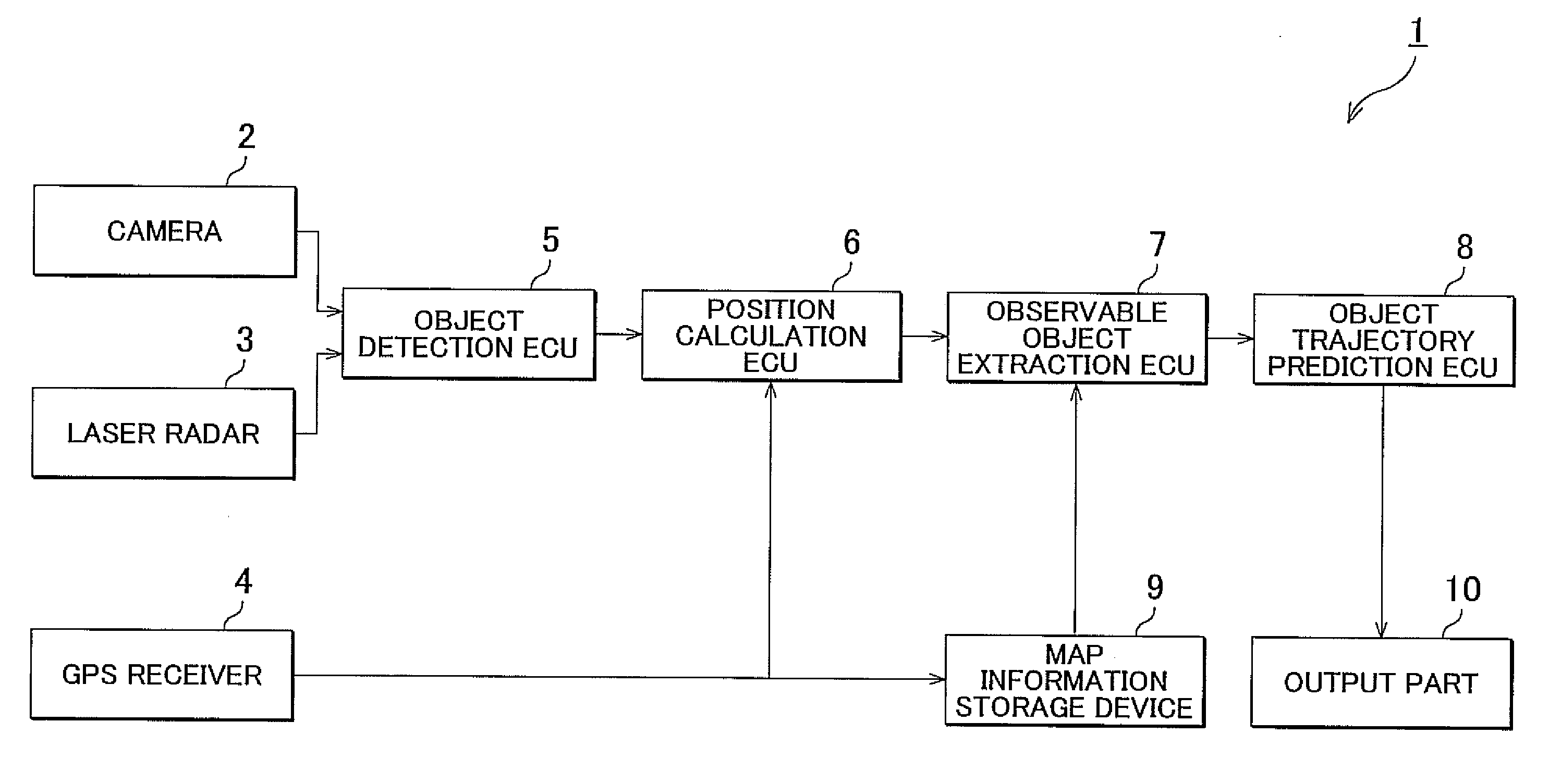
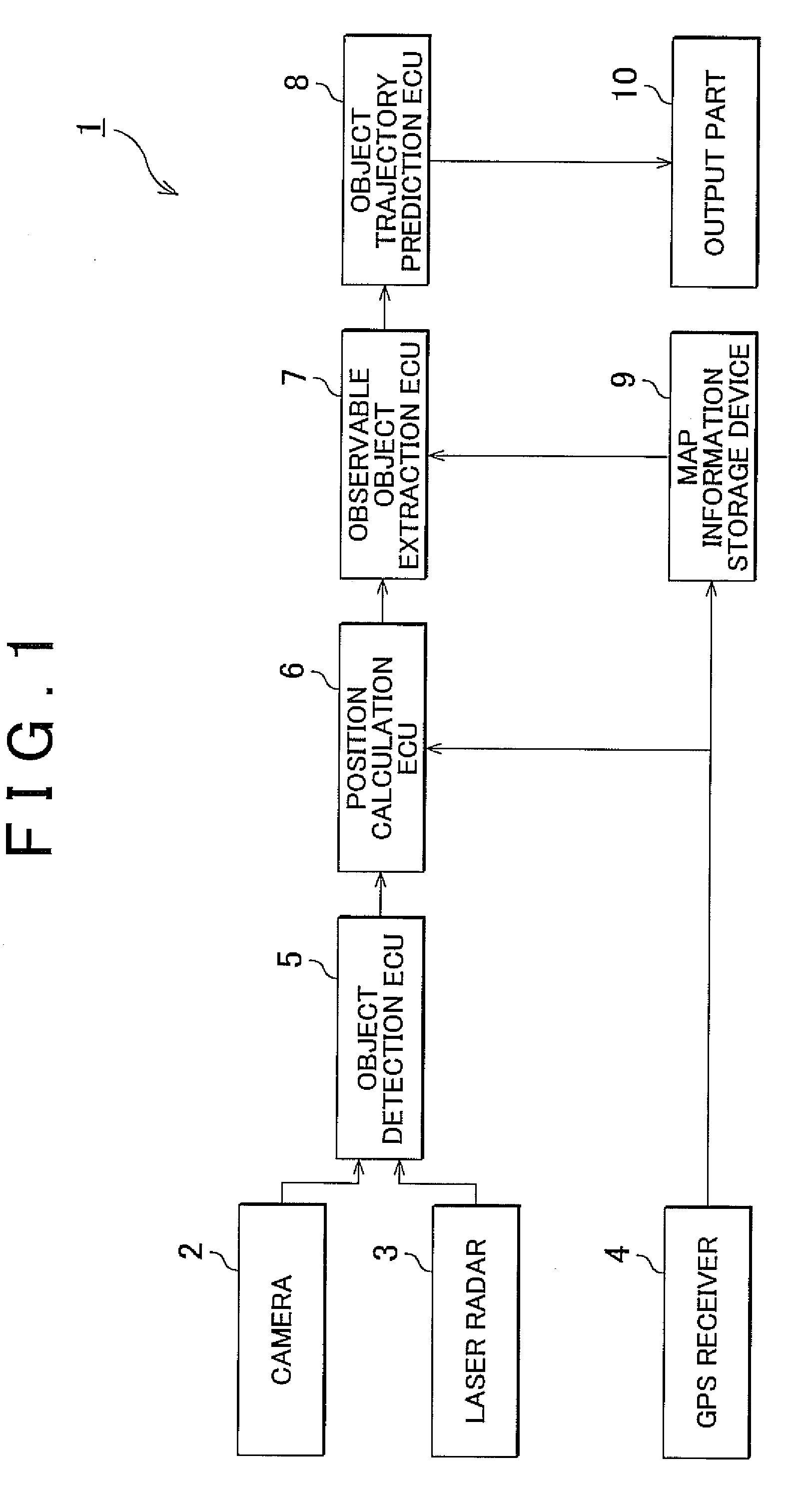
[0022]FIG. 1 is a block diagram showing the structure of the moving object trajectory estimating device according to the first embodiment of the invention. As shown in FIG. 1, the moving object trajectory estimating device I has an object detection electronic control unit (ECU) 5, position calculation ECU 6, observable object extraction ECU 7, and object trajectory prediction ECU 8. The ECUs each execute their own control and are configured by, for example, a central processing unit (CPU), read only memory (ROM), random access memory (RAM), input signal circuit, output signal circuit, power circuit, and the like. The object detection ECU 5 is connected to a camera 2 and laser radar 3. The position calculation ECU 6 is connected with a global positioning system (GPS) receiver 4.
[0023]The camera 2 may be a monocular ca...
second embodiment
[0045]A trajectory estimating method for a moving object according to the invention is described next.
[0046]FIG. 4 is a block diagram showing the structure of a moving object trajectory estimating device according to the second embodiment. As shown in FIG. 4, a trajectory estimating method for a moving object 11 according to the second embodiment differs from the moving object trajectory estimating device 1 according to the first embodiment in that the trajectory estimating method for a moving object 11 has an observed object specifying ECU 12 and receiving device 13. Specifically, the moving object trajectory estimating device 11 has the object detection ECU 5, position calculation ECU 6, observed object specifying ECU 12, and object trajectory prediction ECU 8, and the receiving device 13 is connected with the observed object specifying ECU 12.
[0047]The receiving device 13 communicates with other vehicles around a host vehicle. For example, the receiving device 13 receives vehicle...
third embodiment
[0059]Next, a moving object trajectory estimating device according to the invention will be described.
[0060]FIG. 6 is a block diagram showing the structure of the moving object trajectory estimating device according to the third embodiment. As shown in FIG. 6, a trajectory estimating method for a moving object 16 according to the third embodiment differs from the moving object trajectory estimating device 1 according to the first embodiment in that the trajectory estimating method for a moving object 16 includes a blind spot calculation ECU 17, observed object selecting ECU 18, individual authentication ECU 19, and individual blind spot information database (DB) 20.
[0061]The individual authentication ECU 19 is connected to the object detection ECU 5 and performs individual authentication on the plurality of other vehicles detected by the object detection ECU 5. For example, the individual authentication ECU 19 authenticates the vehicle model by reading an image or license plate of t...
PUM
 Abstract
Description
Claims
Application Information