
Tapered roller bearing apparatus and hub unit

a technology of tapered roller bearings and hub units, which is applied in mechanical equipment, hubs, transportation and packaging, etc., can solve the problems of deterioration, contact with the surface, and the sealing performance of the seal member, so as to prevent the cage from being broken or abraded, and surely prevent the crack occurring in the large rib portion. , to achieve the effect of restricting overheating of the cag

Active Publication Date: 2009-10-08
JTEKT CORP
View PDF14 Cites 5 Cited by
  • Summary
  • Abstract
  • Description
  • Claims
  • Application Information

AI Technical Summary

Benefits of technology

[0011]The present invention is made in consideration of the above-described problem, and an object of the invention is to provide a tapered roller bearing apparatus capable of preventing a crack occurring in the vicinity of a large rib portion while ensuring sealing performance of a seal member, and to provide a hub unit.
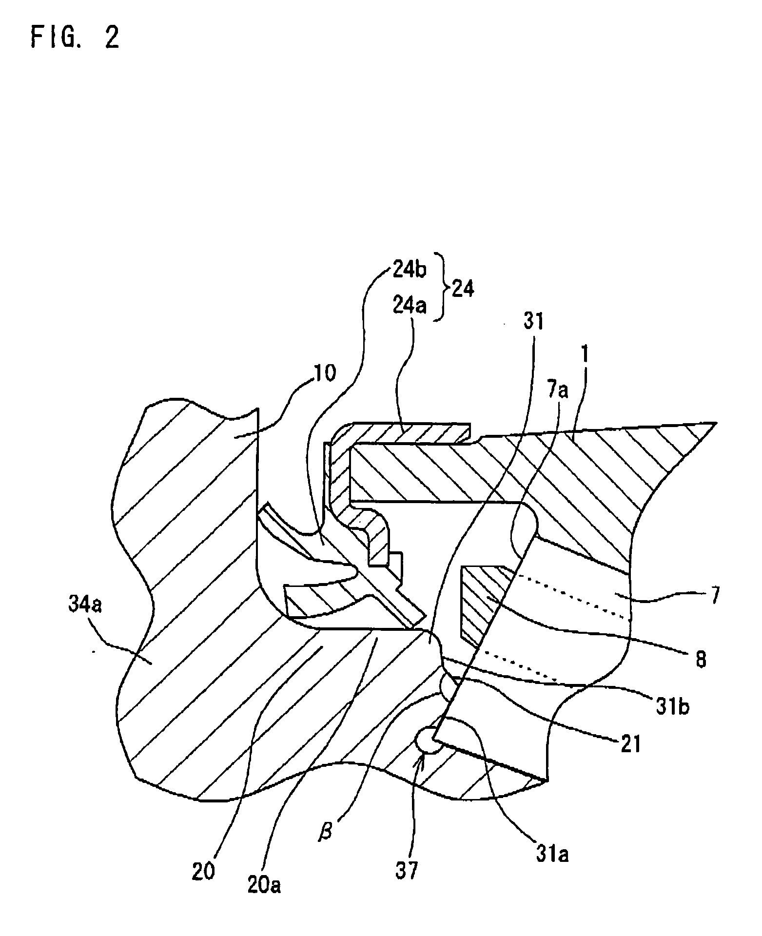
[0028]In the tapered roller bearing apparatus according to the invention, since the large-diameter portion of the inner ring is provided with the cylindrical portion having the substantially uniform outer diameter, it is possible to surely allow the front end of a seal member disposed in the large-diameter portion to come into contact with the outer circumferential surface of the large-diameter portion, thereby ensuring sealing performance of the seal member.
[0029]The concave escaping portion may be formed in the outer circumferential surface of the large rib portion so as to avoid interference of the cage for retaining the tapered roller. With such a configuration, since the concave escaping portion is formed in the outer circumferential surface of the large rib portion, it is possible to prevent the cage from coming into contact with the large rib portion even when the cage moves. Accordingly, it is possible to prevent the cage from being broken or abraded.
[0030]An angle α formed between a line parallel to an axis and the outer circumferential surface of the large rib portion may be in a range of 45°<α<90°. In this case, it is possible to make an obtuse angle of the outer circumferential corner portion of the large rib portion sufficiently large, and thus it is possible to surely prevent a crack occurring in the large rib portion by restricting overheat thereof.
[0031]According to the tapered roller bearing apparatus of the invention, it is possible to prevent a crack occurring in the vicinity of a large rib portion while ensuring sealing performance of a seal member.

Problems solved by technology

However, in the tapered roller bearing apparatus disclosed in JP-A-2005-3111, since the outer circumferential surface of the hub main body is simply formed into the inclined surface from the position around the lower part of the flange portion to the guide surface of the large rib portion in order to allow the outer circumferential corner portion of the large rib portion to be set to an obtuse angle, a problem may arise in that sealing performance of the seal member, which is disposed in the inclined surface while contacting therewith, deteriorates.

Method used


Image

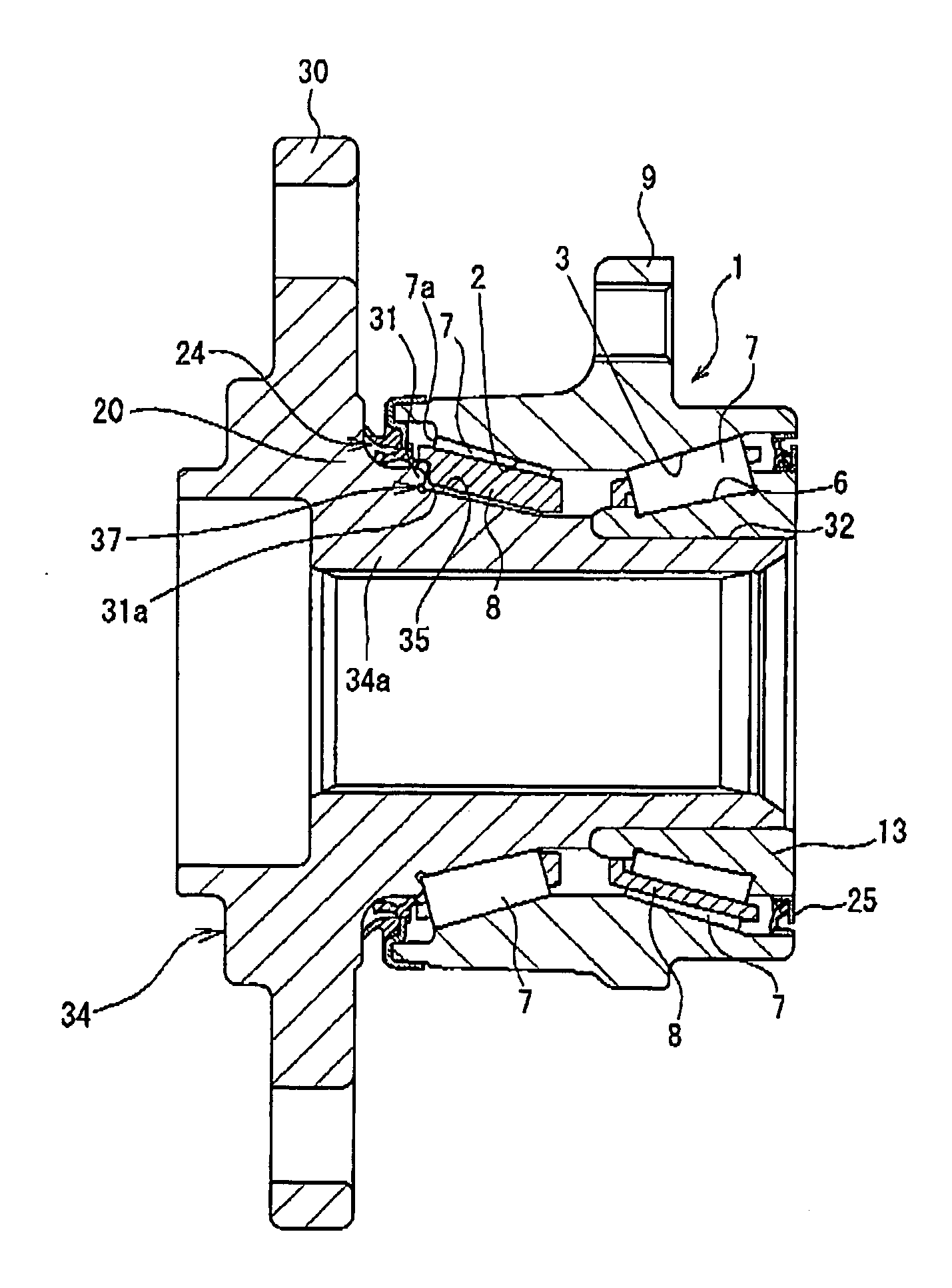
  • Tapered roller bearing apparatus and hub unit
  • Tapered roller bearing apparatus and hub unit
  • Tapered roller bearing apparatus and hub unit

Examples


Embodiment Construction

[0038]Hereinafter, a tapered roller bearing apparatus according to exemplary embodiments of the invention will be described with reference to the accompanying drawings.

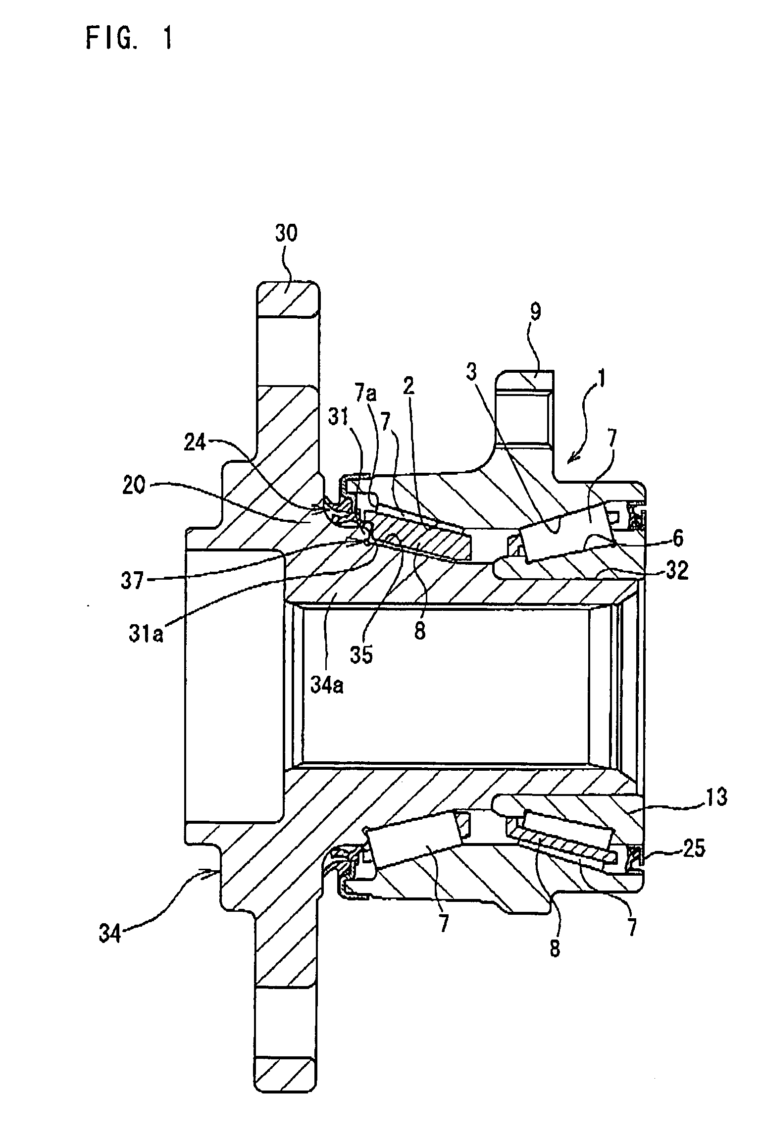
[0039]FIG. 1 is a sectional view illustrating a tapered roller bearing apparatus according to an embodiment of the invention. The same reference numerals are given to the same components or members in that the tapered roller bearing apparatus has the same configuration as that of the known tapered roller bearing apparatus shown in FIG. 6 except for the configuration in the vicinity of a large rib portion and a seal member. As shown in FIG. 1, the tapered roller bearing apparatus according to this embodiment includes first and second outer-ring raceways 2 and 3 which are disposed in the inner circumferential surface of the outer ring 1; first and second inner-ring raceways 35 and 6 which are disposed in the outer circumference of a hub main body 34 as an inner ring so as to be opposed to the first and second outer-ring...


PUM


Abstract

A tapered roller bearing apparatus includes: an outer ring that includes an outer-ring raceway formed in an inner circumferential surface thereof; an inner ring which includes a large-diameter portion having a cylindrical portion with a substantially uniform outer diameter, a large rib portion having an outer circumferential surface and a guide surface continued to the outer circumferential surface, an inner-ring raceway, and a small-diameter cylindrical portion which are sequentially formed from one end to the other end, and are subjected to a heat treatment to have a surface-hardened layer; and a plurality of tapered rollers which are rollably disposed between the inner-ring raceway and the outer-ring raceway, a large-diameter end surface of the tapered roller being guided by the guide surface. An angle formed between the guide surface and the outer circumferential surface is obtuse.

Description

BACKGROUND OF THE INVENTION[0001]The present invention relates to a tapered roller bearing apparatus and a hub unit.[0002]A vehicle wheel is rotatably supported by a rolling bearing with respect to a suspension device. Heavy vehicles such as truck and bus are generally supported by double row tapered roller bearing with respect to the suspension device.[0003]As to the bearing apparatus, there has been proposed a tapered roller bearing apparatus called a third generation hub unit that is designed to reduce a cost by reducing the number of components.[0004]As shown in FIG. 6, the tapered roller bearing apparatus includes first and second outer-ring raceways 2 and 3 which are provided in an inner circumferential surface of an outer ring 1; first and second inner-ring raceways 5 and 6 which are provided in an outer circumference of a hub main body 4 as an inner ring so as to be opposed to the outer-ring raceways 2 and 3; and a plurality of tapered rollers 7 which are arranged between th...

Claims


Application Information

Patent Timeline
IPC IPC(8): F16C33/58F16C33/76
CPCB60B27/001F16C19/225F16C19/386F16C33/585F16C33/7886F16C2326/02F16C33/64F16C33/581
Inventor YAMASHITA, KIICHIROTAKIMOTO, MASAOTSUZAKI, YOUICHI
Owner JTEKT CORP
Learn More