
System and method for communication of multi-mode base stations

a multi-mode base station and communication system technology, applied in the field of wireless communication technologies, can solve the problems of increasing the complexity of the interface, increasing the complexity of maintenance and updating, increasing the operating cost, etc., and achieves the effects of enhancing the switching performance, increasing the rate of successful switching, and greatly improving the system

Inactive Publication Date: 2009-10-08
HUAWEI TECH CO LTD
View PDF13 Cites 62 Cited by
  • Summary
  • Abstract
  • Description
  • Claims
  • Application Information

AI Technical Summary

Benefits of technology

[0007]Accordingly, the present invention provides a system and method for communication of multi-mode base stations, making interaction between multi-mode base stations simpler. The present invention further provides a multi-mode base station of internal communication and a processing method thereof, thus realizing communication between single mode base station sub-nodes in the multi-mode base station.
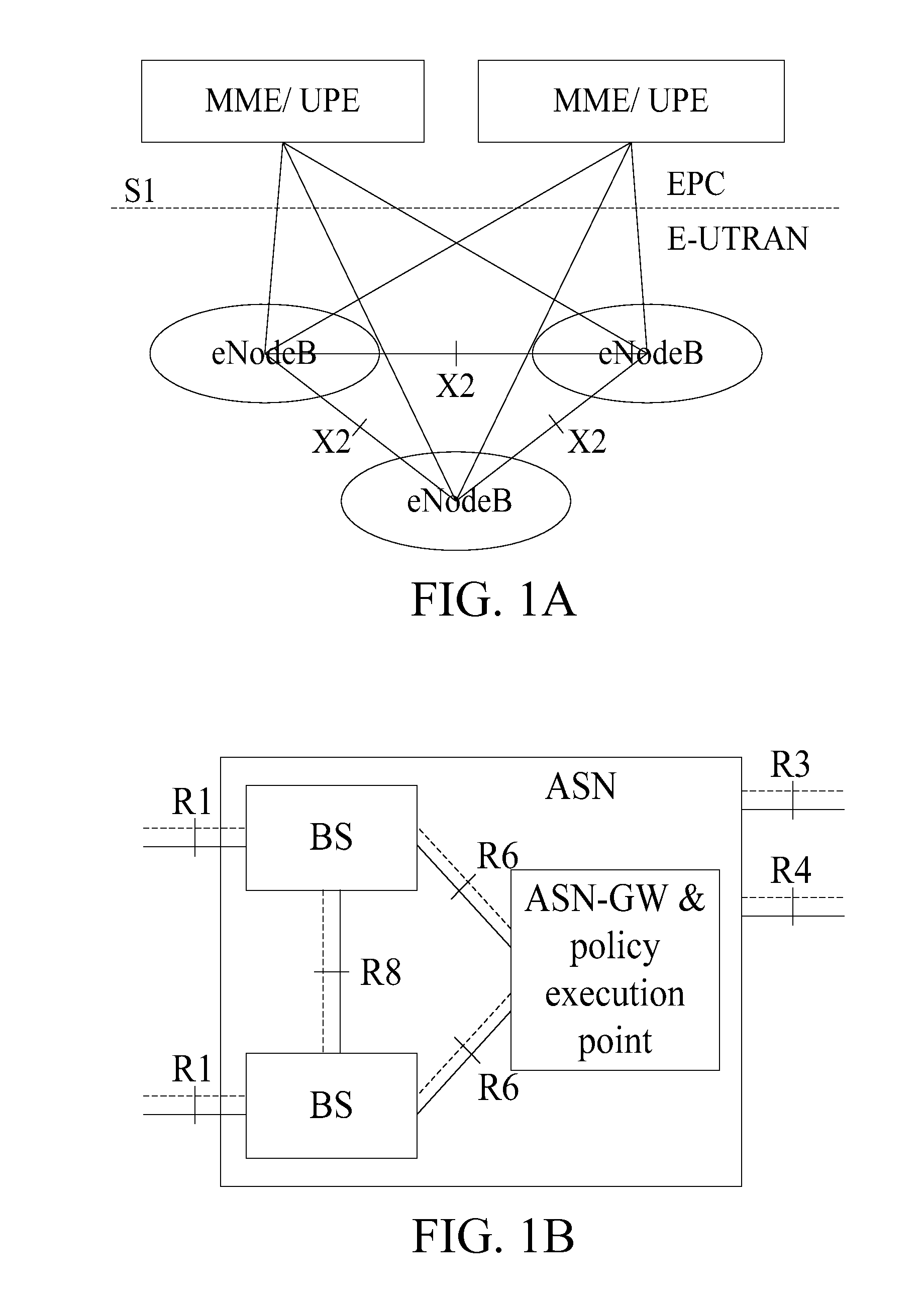
[0012]The embodiments of the present invention further provide an implementation function of the interface unit between base station sub-nodes in the multi-mode base station. A function similar to X2 interface or R8 interface can be provided in the multi-mode base station, the interface may be a logic interface with a uniform transmission protocol stack, or distributed independent logic interfaces. The higher layer application protocol borne on the transmission protocol stack may be a higher layer application protocol originally supported by each single mode base station sub-node, or newly designed uniform higher layer application protocol. After the interface unit provided in the multi-mode base station adopts a uniform protocol stack, if the similar uniform protocol stack is provided between multi-mode base stations, a channel for transmitting protocol between multi-mode base stations and between base station sub-nodes in the multi-mode base station is established, and the performance of the system is thus greatly improved.
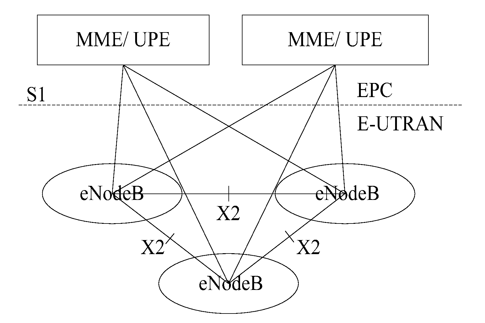
[0013]Additionally, if the multi-mode base stations are communicatively coupled to each other through a multi-mode interface, i.e., the base station sub-nodes of the same mode in different multi-mode base stations are communicatively coupled to each other through a currently defined interface, or connection interfaces exist only when interfaces have been defined currently between base station sub-nodes in the multi-mode base station, here, the base station sub-nodes between which no connection interface exists may interact information with each other through the base station sub-nodes having the connection interfaces, that is to say, an existing interface may transmit information of base station sub-nodes which does not have the connection interface by way of piggybacking. For example, the WiMax base station sub-node transmits interference information through the X2 interface between LTE base station sub-nodes to perform interference coordination. Or, GSM base station sub-nodes or GSM enhanced base station sub-nodes transmit load information through the X2 interfaces between LTE base station sub-nodes, so that when the GSM enhanced base station sub-nodes or BSCs perform cell switching, the load information can be taken into consideration, thus greatly increasing the rate of successful switching and enhancing the performance of switching.

Problems solved by technology

These interfaces between the same mode base stations in different multi-mode base stations may greatly increase the complexity of the interface, and increase the complexity of maintenance and updating, thus dramatically increasing the operating cost.
Unlike the LTE system, handover between these base stations is unable to exchange the load information between the base stations through the X2 interface, so the handover request has blindness to some degree, and the rate of handover failure will be higher.

Method used


Image

  • System and method for communication of multi-mode base stations
  • System and method for communication of multi-mode base stations
  • System and method for communication of multi-mode base stations

Examples


first embodiment

[0039]FIG. 3B is a first schematic drawing of a control plane transmission protocol stack according to the present invention. As shown in FIG. 3B, the control plane transmission protocol stack includes a layer 1, a layer 2, an IP layer, a simple control transmission protocol (SCTP) layer, and a uniformly defined multi-mode uniform control plane protocol layer. In this way, specifically, a certain base station sub-node in the multi-mode base station sending control information may encapsulate the control information in turn according to the control plane transmission protocol stack, and send the control information. Specifically, a certain base station sub-node in the multi-mode base station receiving the control information may decapsulate the received control information in turn according to the control plane transmission protocol stack, acquire the content of the control information, and then perform corresponding operations according to the content of the control information. It ...

second embodiment

[0047]FIG. 4A is a schematic drawing of connections between base station sub-nodes in a multi-mode base station according to the present invention. As shown in FIG. 4A, the base station sub-nodes 11, 12 and 13 in the same multi-mode base station are communicatively coupled to each other through an interface unit 1, the base station sub-nodes 21 and 22 in the same multi-mode base station are communicatively coupled to each other through an interface unit 2, and so on. Each interface unit provides a basal physical transmission bearer for transmitting a higher layer application protocol. The base station sub-nodes communicatively coupled to each other through the same interface unit may support the same RAT, or different RATs. If the base station sub-nodes communicatively coupled to each other through the same interface unit support the same RAT, and the connection interface exists between the existing base stations supporting the corresponding RAT, the interface unit can employ the ex...

third embodiment

[0054]FIG. 5 is a schematic drawing of connection between the base station sub-nodes in the multi-mode base station according to the present invention. As shown in FIG. 5, the base station sub-nodes in the same multi-mode base station are communicatively coupled to each other through a uniform interface unit that provides a basal physical transmission bearer and a uniform transmission protocol stack namely uniform logic interface for transmitting a higher layer application protocol. In this way, the different base station sub-nodes in the same multi-mode base station transmit the higher layer application protocol though a uniform interface. The higher layer application protocol at least includes a control plane protocol and a use plane protocol. The functions implemented by the interface unit between the base station sub-nodes in the same multi-mode base station mainly include a control plane and a user plane. The control plane is used for interaction of control information, such as...


PUM


Abstract

A system and method for communication of multi-mode base stations is provided. The multi-mode base stations are communicatively coupled to each other through a uniform interface unit that provides a basal physical transmission bearer and a uniform transmission protocol stack, namely uniform logic interface, for transmitting a higher layer application protocol to support information interaction, such as load information, resource usage information, interference information, handover flow signaling information, data forwarding, between multi-mode base stations even base station sub-nodes in each multi-mode base station. The higher layer application protocol borne by the uniform transmission protocol stack is mainly a user plane protocol and a control plane protocol. The implementation function of the interface unit between base station sub-nodes in the multi-mode base station is further provided. When the interface unit provided by the multi-mode base station uses a uniform protocol stack, if the similar uniform protocol stack is provided between multi-mode base stations, the performance of the system can be greatly improved.

Description

[0001]The present application claims the priority to Chinese Patent Application No. 200610167280.0, filed on Dec. 15, 2006 and entitled “Base station, and System and Method for Communication of Multi-mode Base Stations”, the content of which is incorporated herein by reference in its entirety.FIELD OF THE INVENTION[0002]The present invention relates to the field of wireless communication technologies, and particularly to a system and a method for communication of multi-mode base stations.BACKGROUND OF THE INVENTION[0003]With the development of wireless communication technologies, more and more radio access technologies (RATs) are applied. These different RATs include global system for mobile (GSM) technology, wideband code division multiple access (WCDMA) technology, world interoperability for microwave access (WiMax) technology, long term evolution (LTE) technology, air interface evolution (AIE) technology, code division multiple access (CDMA) 2000 technology etc. These different r...

Claims


Application Information

Patent Timeline
IPC IPC(8): H04W88/08H04M1/00H04W92/00H04W88/10
CPCH04W36/0055H04W92/20H04W88/10H04W36/0079H04W36/0064
Inventor QIU, YONGXIE, MINGJIANGDENG, YONGFENG
Owner HUAWEI TECH CO LTD
Learn More