Low profile implant locking plates

a low-profile, locking plate technology, applied in the field of implants, can solve the problems of pain to patients, failure of bone fusion, and tension of prosthesis migration

Inactive Publication Date: 2009-10-08
PAZANOWSKI WALT +2
View PDF2 Cites 4 Cited by
  • Summary
  • Abstract
  • Description
  • Claims
  • Application Information

AI Technical Summary

Benefits of technology

[0014]In still yet another embodiment, the elongated body includes a cover portion disposed to at least partially overla

Problems solved by technology

Unfortunately, because of the continuous forces that act upon the vertebrae and especially the disc prosthesis there is a tendency for the prosthesis to migrate due to shifting, rotation or slippage.
Obviously, such movement can result in pain to the pati

Method used


Image

  • Low profile implant locking plates
  • Low profile implant locking plates
  • Low profile implant locking plates

Examples


Embodiment Construction

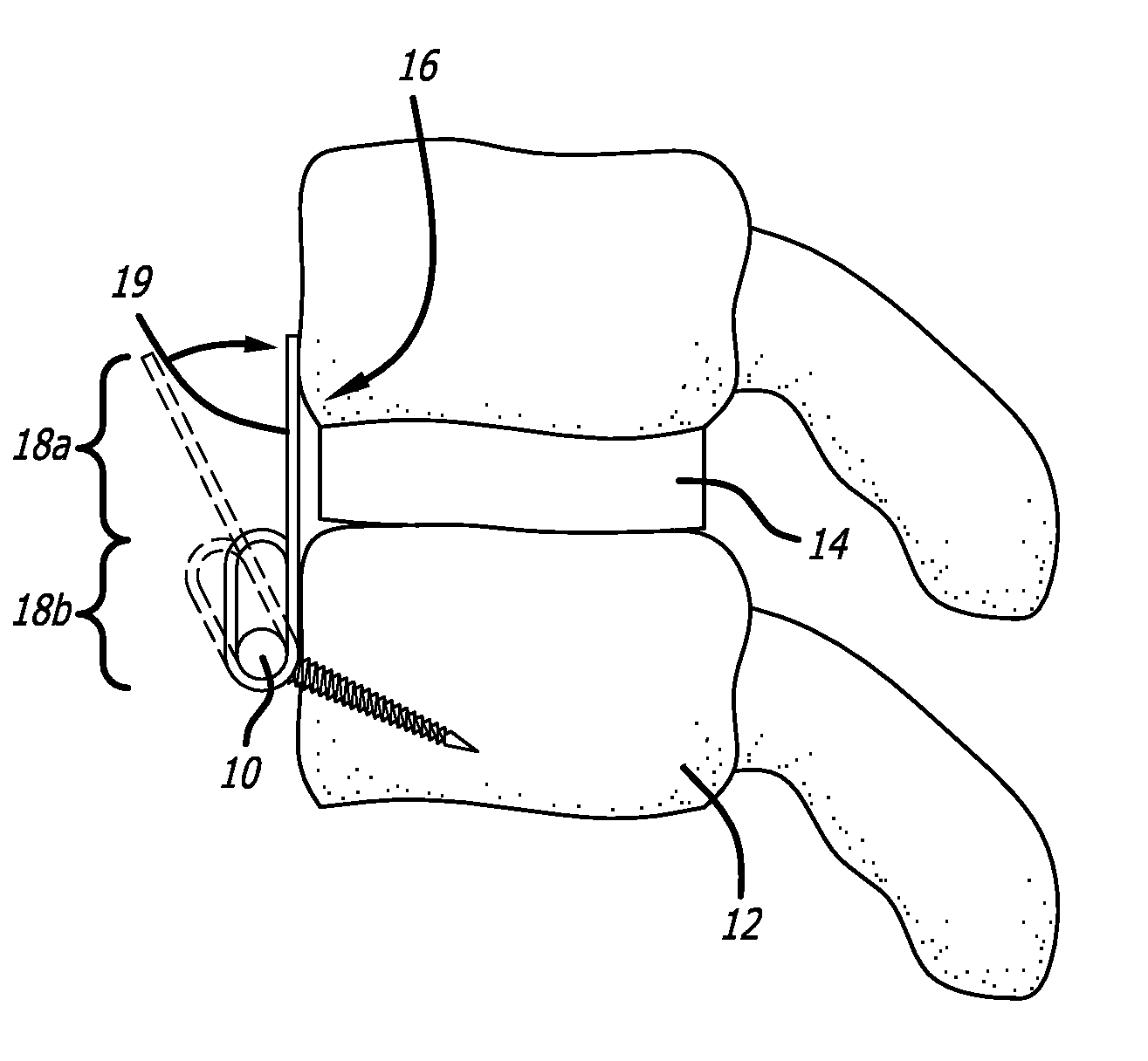
[0024]In an anterior lumbar spinal surgery it is often common to insert an implant, such as an artificial disc or bone graft, into a collapsed disc space to reestablish the spacing and curvature of the spine. However, when a patient begins to move and the effects of gravity begin to assert itself on the bone graft it can slip forward and “fall out” of the disc space. The current invention provides a system of implant locking plates that may be anteriorly secured to a vertebral body to stabilize the bone graft and ensure that it cannot slip out of the disc space.

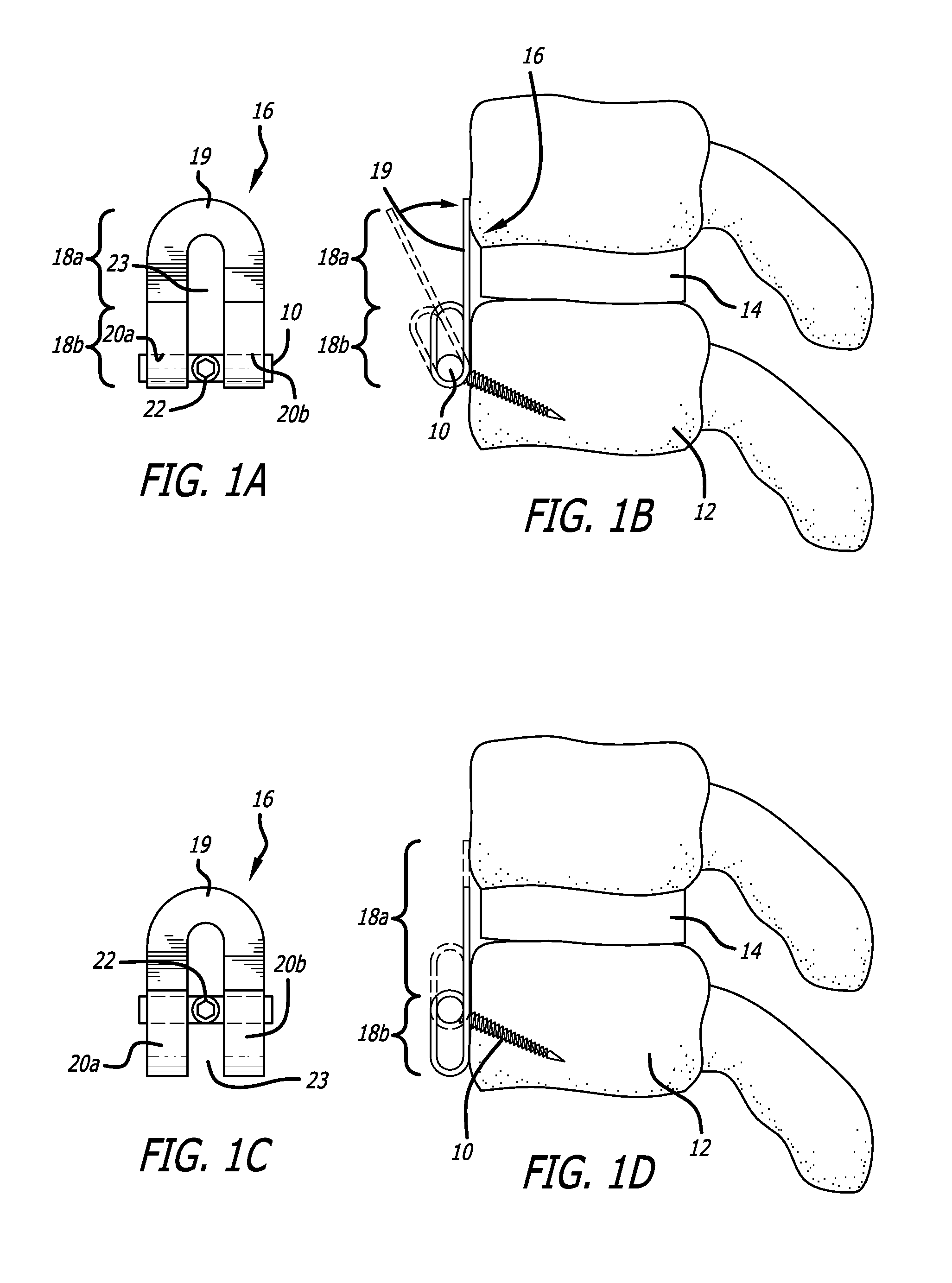
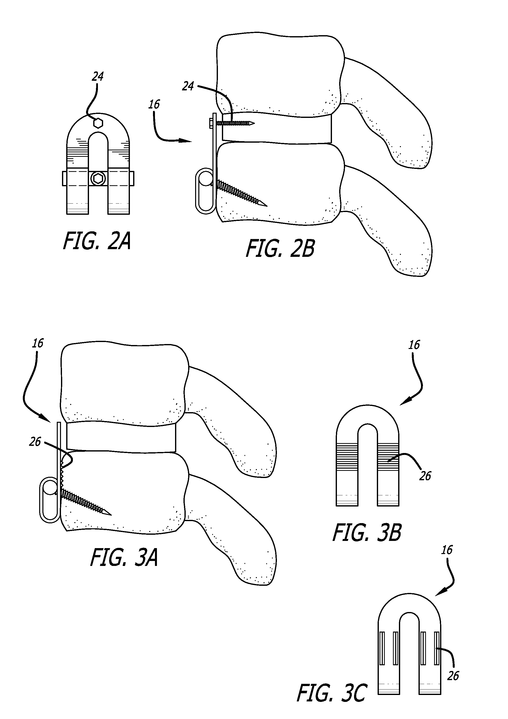
[0025]Specifically, the current invention is directed to an implant locking plate system that generally includes at least one “T”-headed bone anchoring means, such as a screw or bolt, that can be inserted into a vertebral body adjacent to the artificial disc to be stabilized, and a stabilizing plate attached to the bone anchoring means designed to overlap at least a portion of the artificial disk or graft when the bone anchor...


PUM


Abstract

An implant locking plate system and a method of using such a system are provided. The implant locking plate system generally includes at least one “T”-headed bone anchoring means, such as a screw or bolt that can be inserted into a vertebral body adjacent to the artificial disc to be stabilized, and a stabilizing plate attached to the bone anchoring means designed to overlap at least a portion of the artificial disk or graft when the bone anchor is inserted into the vertebral body adjacent to the artificial disk or graft.

Description

CROSS-REFERENCE TO RELATED APPLICATIONS[0001]The current application claims priority to U.S. Provisional Application No. 61 / 020,864, filed Jan. 14, 2008, the disclosure of which is incorporated herein by reference.FIELD OF THE INVENTION[0002]The current invention is directed to an implant locking plate; and particularly to low profile adjustable implant locking buttress and fusion plates.BACKGROUND OF THE INVENTION[0003]Intervertebral discs are fibrous cartilage pads that allow the spine to bend and serve as “shock” absorbers for the vertebrae, absorbing pressure delivered to the spinal column. Additionally, they maintain the proper anatomical separation between two adjacent vertebras. This separation is necessary for allowing nerves to exit and enter unimpeded from the spinal column.[0004]To alleviate the pain caused by a damaged disc, current treatment methods include a discectomy in which the affected intervertebral disc is removed and an interbody fusion implant is inserted. The...

Claims


Application Information

Patent Timeline
IPC IPC(8): A61B17/80A61B17/86
CPCA61B17/7059A61B17/8605A61B17/809
Inventor PAZANOWSKI, WALTMCKINLEY, LAURENCE M.PEPPERS, TIMOTHY ALLEN
Owner PAZANOWSKI WALT
Why Eureka
Try Eureka