
Method for analyzing strain data

Active Publication Date: 2009-10-08
BAKER HUGHES INC
View PDF33 Cites 48 Cited by
  • Summary
  • Abstract
  • Description
  • Claims
  • Application Information

AI Technical Summary

Benefits of technology

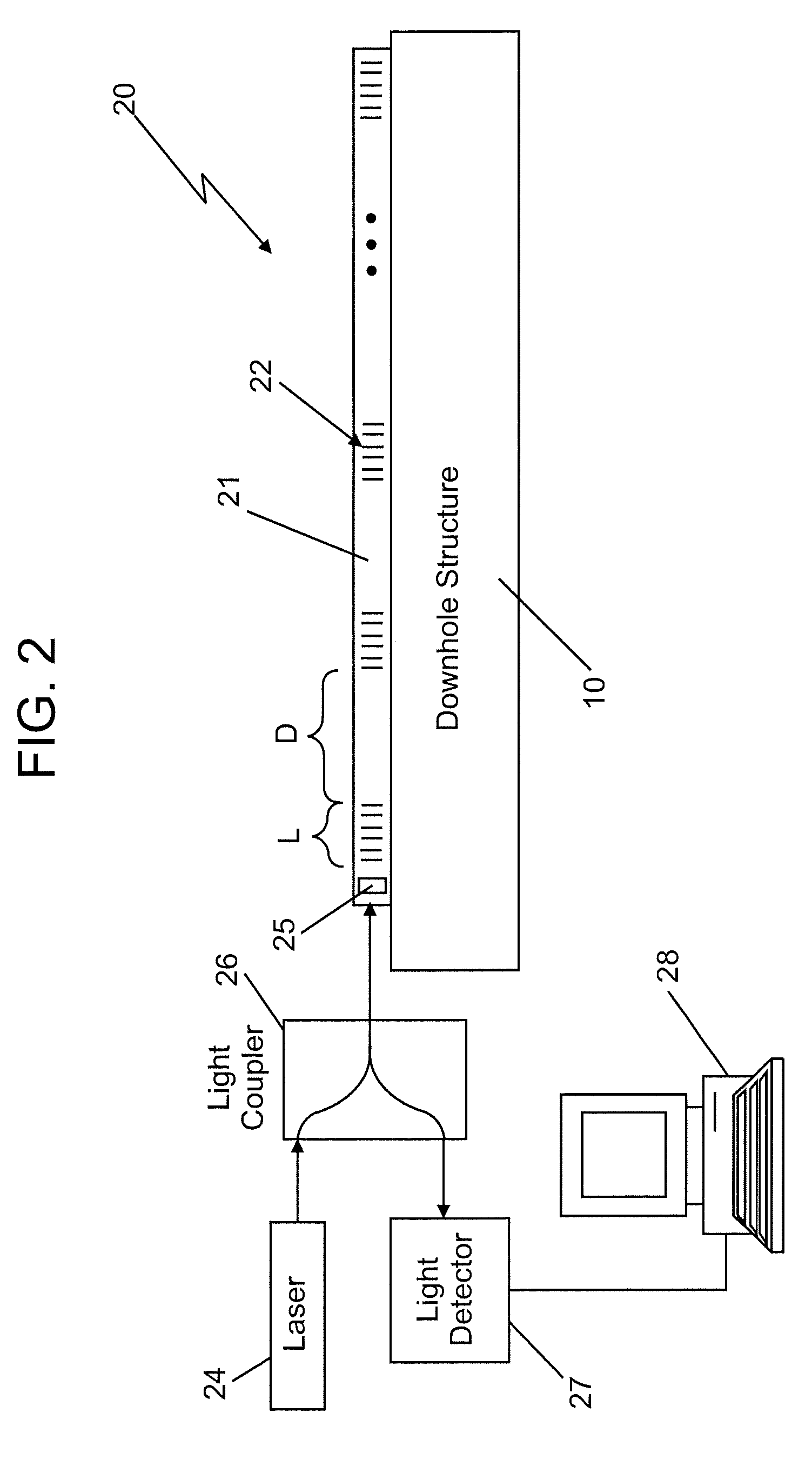
The patent describes a method for estimating the shape of a downhole structure using strain sensors placed on the structure. The strain sensors provide measurements that are used to create a mesh grid with nodes that are related to the location of the strain sensors and assigned a strain value. Additional nodes are created based on the strain values of adjacent nodes. An inverse finite method is then used to estimate the shape of the downhole structure based on the strain values of the mesh grid. The system and computer program product described in the patent make it possible to accurately estimate the shape of downhole structures, which can aid in the design and construction of downhole tools and structures.

Problems solved by technology

However, depending on the number of sensors, locations of the sensors, and discontinuities in the data, it is possible for the algorithm not to converge on an accurate solution and, therefore, not determine the shape.

Method used


Image

  • Method for analyzing strain data
  • Method for analyzing strain data
  • Method for analyzing strain data

Examples


Embodiment Construction

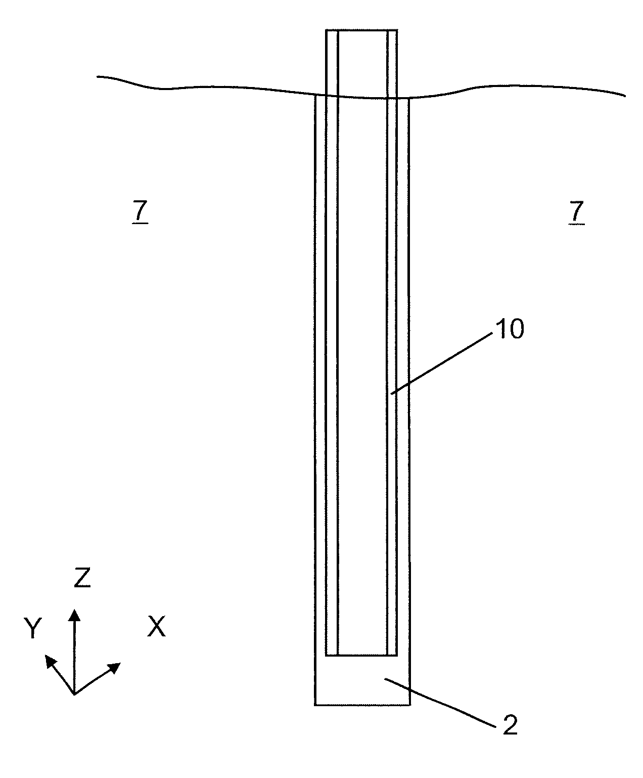
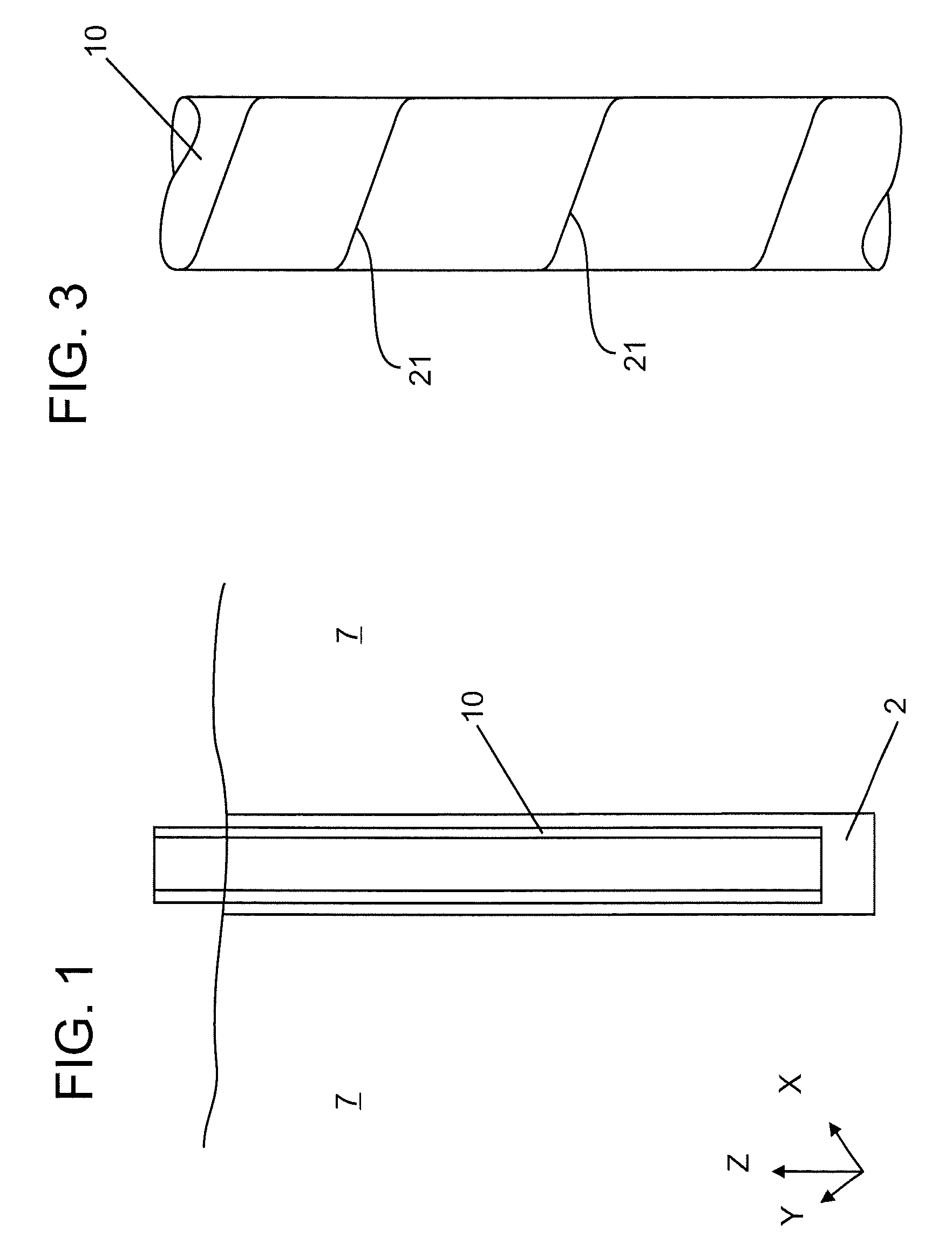
[0018]Disclosed are exemplary techniques for accurately estimating a shape of a downhole structure. The techniques, which include apparatus and method, use a plurality of strain sensors. The strain sensors measure strains experienced by the downhole structure at the locations of the sensors. A processing system uses an algorithm to process measurements from the strain sensors to provide the shape (or deformation) of the downhole structure.

[0019]Normally if a known load is applied to a structure, the resulting strain experienced by the structure can be calculated via a finite element analysis. However, when the load is unknown such as in a downhole environment and the strains as measured by the strain sensors are known, then an inverse finite element method is used to estimate the deformation or the new shape resulting from the strains. The inverse finite element method can be implemented with commercially available mathematics computer programs such as MATLAB® from The MathWorks of ...


PUM


Abstract

A method for estimating a shape, the method including: selecting a structure comprising a plurality of strain sensors inoperable communication with the structure, each strain sensor configured to provide a strain measurement; placing the structure in a borehole; receiving the strain measurements from the plurality of strain sensors; creating a mesh grid having nodes, each node related to a location of one strain sensor and assigned a strain value measured by the one strain sensor; creating an additional node for the mesh grid wherein a strain value assigned to the additional node is derived from the strain value corresponding to at least one adjacent node; and performing an inverse finite method using the mesh grid with the assigned strain values to estimate the shape.

Description

BACKGROUND OF THE INVENTION[0001]1. Field of the Invention[0002]This invention relates to structural damage detection systems for structures in a borehole and, more particularly, to structural damage detection systems utilizing optical fibers.[0003]2. Description of the Related Art[0004]Exploration and production of hydrocarbons generally require a borehole be drilled into a geologic formation. Various structures may be called upon to be inserted into the borehole as part of the exploration and production. Examples of these structures include a borehole casing and a sand screen.[0005]Due to instabilities in the formation such as reservoir compaction, the formation may exert a force on a downhole structure high enough to deform the structure. If the downhole structure is deformed, it is important to know the extent of the deformation. By having knowledge of the deformation, mitigating or corrective actions can be initiated.[0006]One method to measure a deformation is to attach strain...

Claims


Application Information

Patent Timeline
Patent Type & Authority Applications(United States)
IPC IPC(8): G01V8/00G02B6/00
CPCG02B6/0208E21B49/006
Inventor STOESZ, CARL W.
Owner BAKER HUGHES INC
Learn More