Operating Device for Exchanging data With a field Device in an Automation System

Active Publication Date: 2009-10-08
SIEMENS AG
View PDF13 Cites 5 Cited by
  • Summary
  • Abstract
  • Description
  • Claims
  • Application Information

AI Technical Summary

Benefits of technology

[0006]An object of the invention is to reduce the effort required in the exchange of data between the operating device and the field device.
[0008]Because of the synchronization of the status unit by the state machine, the operating device always adopts the same status as the field device, so that the current state of the field device is known to the operating device. Data items related exclusively to the state therefore no longer need to be exchanged between the two devices, thereby significantly reducing the scope of the data to be exchanged. For example, if the field device is in a state in which pressure measurement values are to be transmitted to the operating device, it is sufficient to transmit purely the numeric values, because the operating device knows that the numeric values it receives are pressure measurement values and not, say, flow volume measurement values or parameter values.

Problems solved by technology

For a complex exchange of data between the operating device and the field device, if for example there is need to transmit commands and parameters from the operating device to the field device, and responses or acknowledgements together with process measurement values and device data in the reverse direction from the field device to the operating device, often using demanding transmission protocols, a considerable level of additional processor power and energy must be provided in the field device.

Method used


Image

  • Operating Device for Exchanging data With a field Device in an Automation System
  • Operating Device for Exchanging data With a field Device in an Automation System

Examples


Embodiment Construction

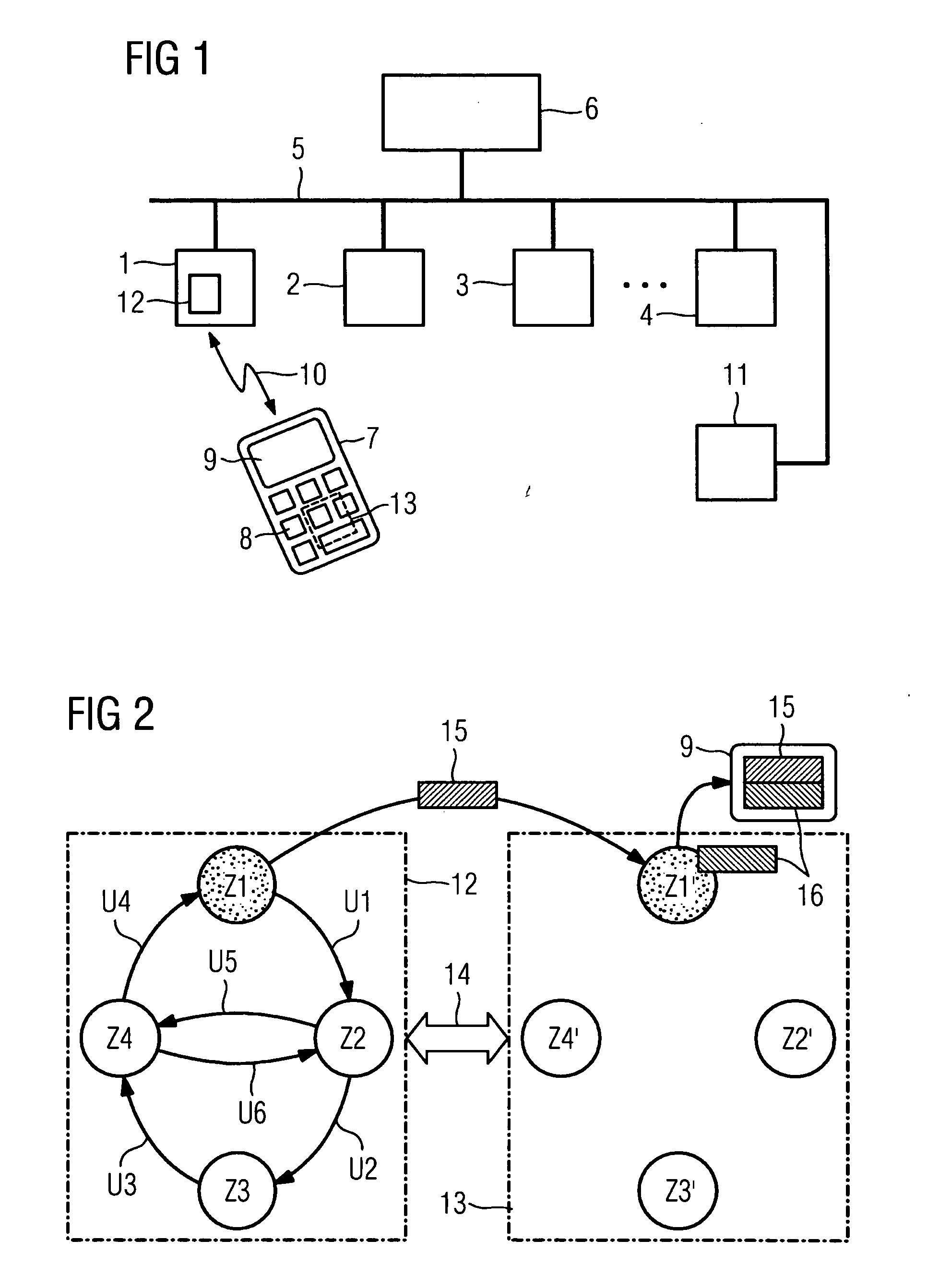
[0017]FIG. 1 shows an automation system with a field device 1, for example a transducer, which together with other field and automation devices 2, 3 and 4 is linked via a communication bus 5 with a higher level control facility 6. When the automation system is in production mode, user data is exchanged between the components 1 to 4 and 6 via the communication bus 5.

[0018]A portable operating device 7 (so-called handheld PC) with operating elements 8 and a display facility 9 is designed for communicating with each one of the field devices 1 to 4 individually via a radio link 10. This communication can take place directly with the field devices 1 to 4 or via an access point 11, which is also connected to the bus 5.

[0019]The field devices 1 to 4 can be parameterized via the operating device 7 which, for this purpose, enables parameters for the field devices 1 to 4 to be input, amended and verified and commands to be input, via the operating elements 8 and the display facility 9. Apart ...


PUM


Abstract

An operator panel having a state unit is provided, wherein individual states of the state unit correspond to states of a state machine contained in a field device and which are synchronized by the state machine in such a way that the actual state of the operator panel corresponds to the actual state of the field device. The operator panel is in the same state as the field device such that the operator panel knows the actual state of the field device.

Description

CROSS-REFERENCE TO RELATED APPLICATIONS[0001]This application is the US National Stage of International Application No. PCT / EP2007 / 054511 filed May 10, 2007 and claims the benefit thereof. The International Application claims the benefits of German application No. 10 2006 021 767.5 DE filed May 10, 2006. Both of the applications are incorporated by reference herein in their entirety.FIELD OF INVENTION[0002]The invention relates to an operating device for exchanging data with a field device in an automation system.BACKGROUND OF INVENTION[0003]In automation systems for engineering or industrial plants, e.g. in the process industry, production and manufacturing industry, building services technology or network technology, locally distributed, decentralized field devices (process devices) perform prescribed functions in the plants concerned, as part of the plant automation, and in doing so exchange process, plant and / or device-related data, between one another when necessary but always ...

Claims


Application Information

Patent Timeline
IPC IPC(8): G06F15/16
CPCG05B19/045G05B2219/14087G05B2219/2609G05B2219/25484G05B2219/23289
Inventor GROSS, STEFAN
Owner SIEMENS AG
Why Eureka
Try Eureka