Instrument

a technology of instruments and mounting brackets, applied in the field of dismountable instruments, can solve the problems of increasing the possibility of complete sterilization and neglecting the dismounting of instruments, and achieve the effect of small risk of unintentional dismounting and good precision

Inactive Publication Date: 2009-10-15
SUNDTORP INNOVATION
View PDF19 Cites 23 Cited by
  • Summary
  • Abstract
  • Description
  • Claims
  • Application Information

AI Technical Summary

Benefits of technology

[0020]Thanks to such a shape conformance, it is easy to get good precision when the pin is to be screwed out or in thanks to the fact that there is no play in the rotary motion. It should be appreciated that with corresponds is meant that there is a sufficient gap to allow the pin to be inserted into the hole.
[0021]In addition, this entails that the angular position that allows axial displacement of the branches in relation to each other becomes precisely defined so that the risk of unintentional dismounting becomes small.

Problems solved by technology

By the simple dismounting, the risk that dismounting of the instrument is neglected when it is to be sterilized decreases, which increases the possibility of a complete sterilization.

Method used


Image

  • Instrument
  • Instrument
  • Instrument

Examples


Embodiment Construction

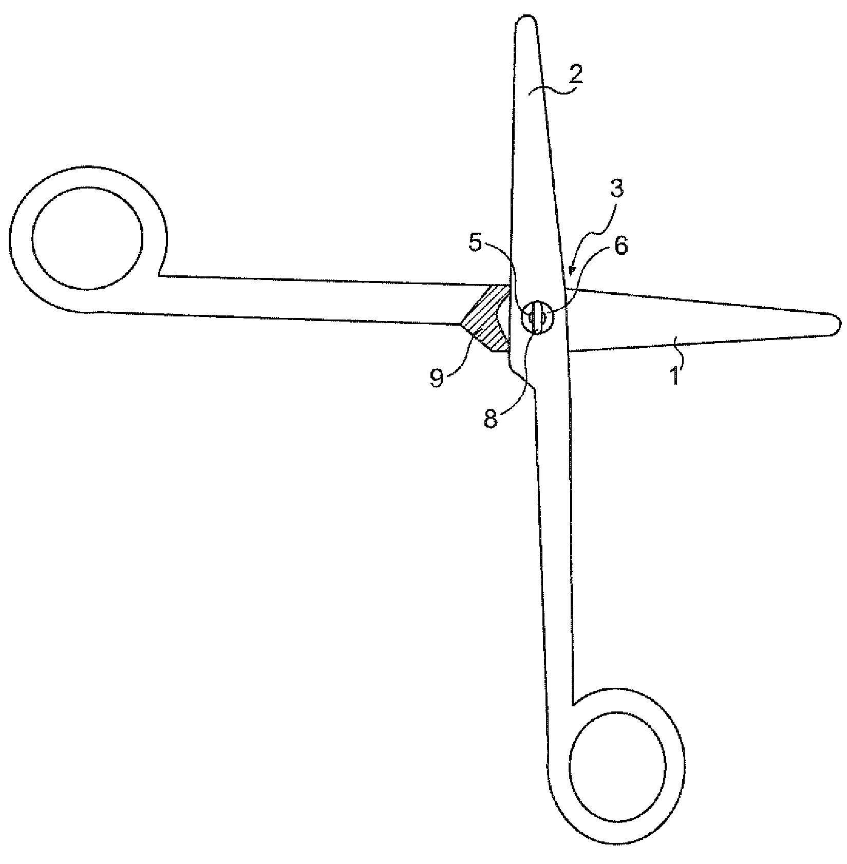
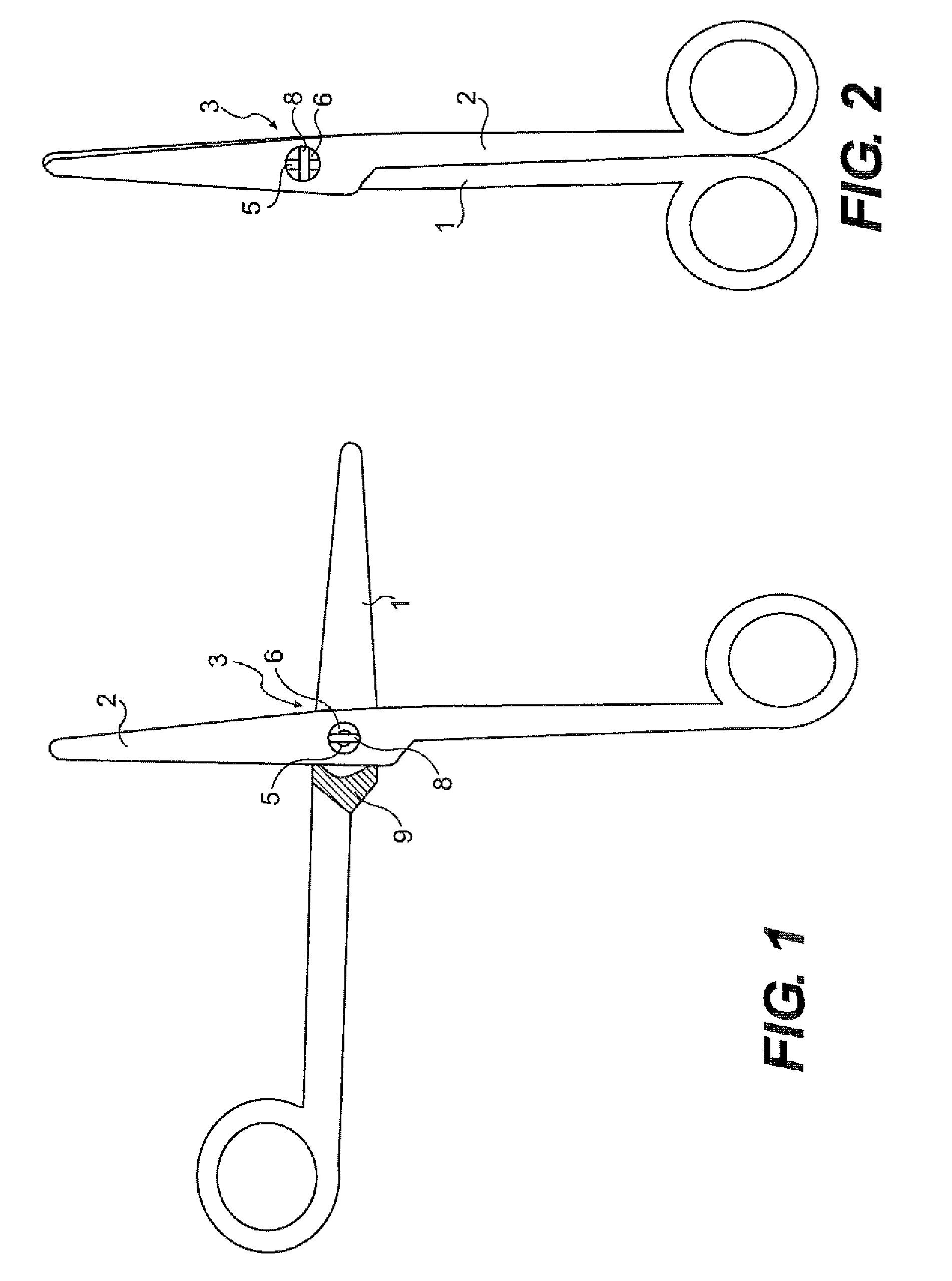
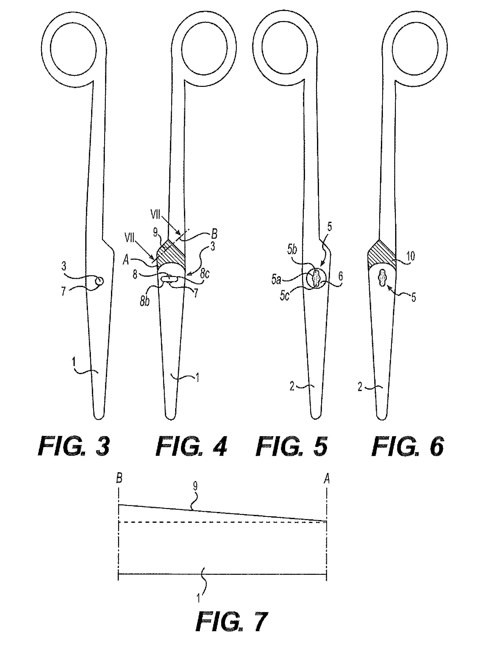
[0043]In FIG. 1, a pair of surgical scissors is illustrated in a side view in a pivotal position with the two branches 1, 2 being essentially perpendicular to each other. The branches are pivotably connected with a coupling element 3, which is fixedly connected with the first branch 1 and extends through a hole 5 in the second branch 2. In the position shown in the figure, the two branches can be dismounted from each other in the axial direction by the fact that a locking body 8 of the coupling element 3 can pass through the hole 5 having a complementary shape. The inside of the branch 1 is provided with a contact surface 9 arranged for cooperation with a corresponding contact surface on the inside of the second branch.

[0044]FIG. 2 illustrates the same pair of scissors in the same side view but with the branches 1, 2 in a maximally collapsed position with the same being essentially parallel to each other. In this position, the two branches are held to each other as a consequence of ...


PUM


Abstract

An instrument having two branches such as a pair of scissors, or the like. The two branches thereof are connected with a coupling element, which is attached to one of the branches and extends through a hole in the other branch. The coupling element has a locking body situated on the outside of the other branch. Both the locking body and the hole are out of round so that the locking body can be brought through the hole in a certain angular position but not in another. According to the invention, the coupling element is screwed into the first branch. Furthermore, the locking body has a shape that is adapted in such a way to the shape of the hole that the coupling element can be turned by means of the second branch.

Description

FIELD OF THE INVENTION[0001]In a first aspect, the present invention relates to a dismountable instrument, such as, for instance, a pair of scissors, a pair of pliers, a pair of artery forceps, needleholder, or vascular clamp comprising a first branch, a second branch pivotable in relation to the first branch, and a coupling element connecting the branches, which coupling element consists of a circular-cylindrical pin attached to the first branch and provided with a locking body that extends radially outside the pin, which second branch is provided with a through hole through which the pin extends so that the locking body of the pin is situated on the side of the second branch that is facing away from the first branch, the radial extension of which locking body varies in the peripheral direction and which hole has a shape that comprises at least one circular-cylindrical wall portion and at least one wall portion situated radially outside the circular-cylindrical wall portion in such...

Claims


Application Information

Patent Timeline
Patent Type & Authority Applications(United States)
IPC IPC(8): B26B13/28
CPCA61B17/2816A61B2019/4868A61B2017/0046A61B17/3201A61B2090/0813
Inventor JALMBERGER, ANDERS
Owner SUNDTORP INNOVATION
Why Eureka
Try Eureka