
Clothes dryer apparatus with improved lint removal system

a clothes dryer and lint removal technology, applied in the direction of drying machines, lighting and heating apparatus, furnaces, etc., can solve the problems of requiring extra space, high cost of coaxial ducting and separate filters, etc., to maximize energy transfer, reduce the air velocity of the air supply, and maximize the contact time of the air supply

Inactive Publication Date: 2009-10-15
PELLERIN MILNOR
View PDF5 Cites 23 Cited by
  • Summary
  • Abstract
  • Description
  • Claims
  • Application Information

AI Technical Summary

Benefits of technology

"The present invention is a lint collector with an air heat exchanger that uses energy from the exhaust stream air to preheat the air supply to the dryer. The air velocity of the air supply is reduced to maximize energy transfer by creating a turbulent annular vortex. This design saves space and cost compared to separate filters and coaxial ducting. It is also more efficient in recovering energy due to the low air flow velocity and use of a vortex."

Problems solved by technology

Current technology lint collectors for industrial dryers typically only perform the function of removing lint from the exhaust air stream.
Such coaxial ducting and separate filters are costly and require extra space.

Method used


Image

  • Clothes dryer apparatus with improved lint removal system
  • Clothes dryer apparatus with improved lint removal system

Examples


Embodiment Construction

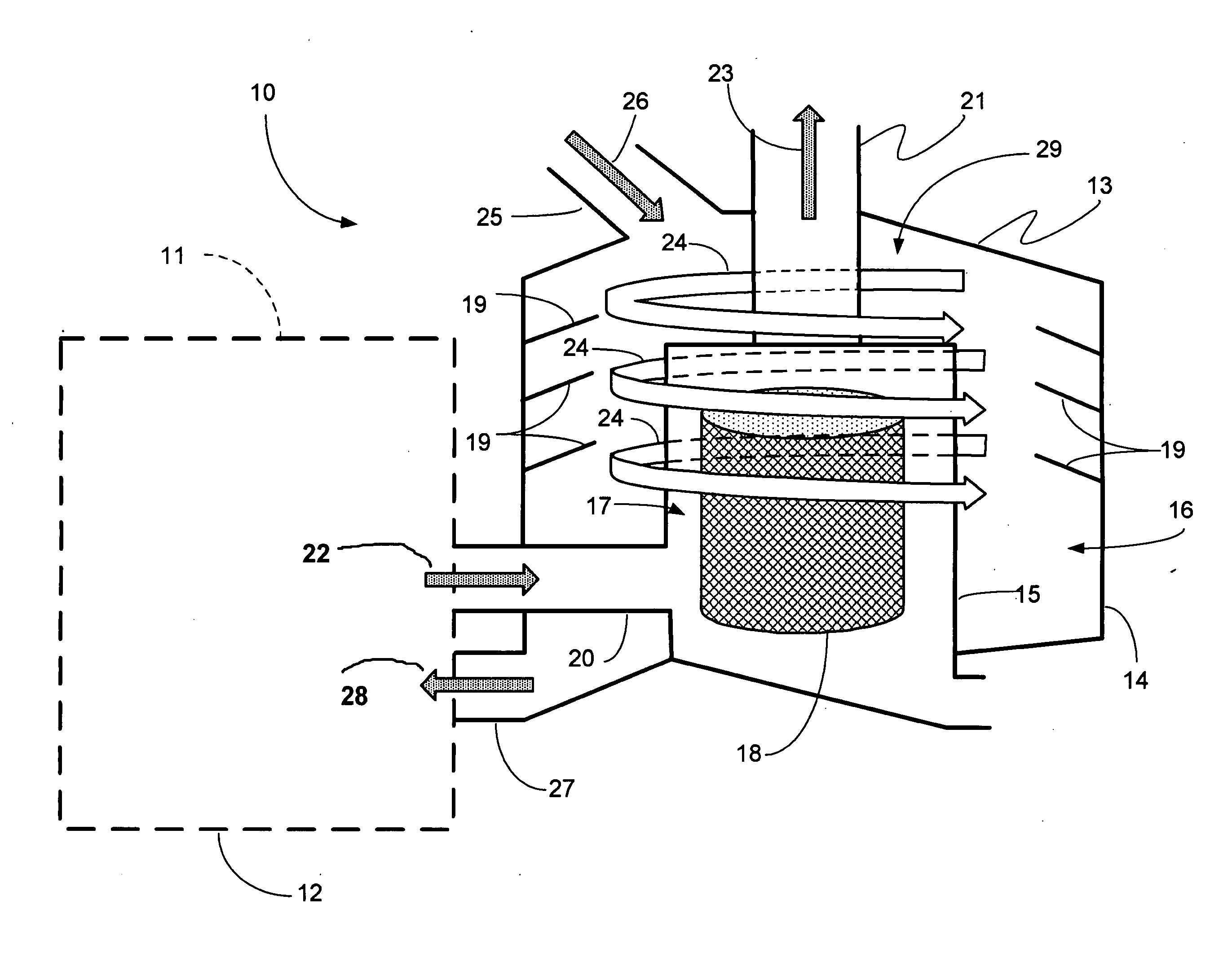
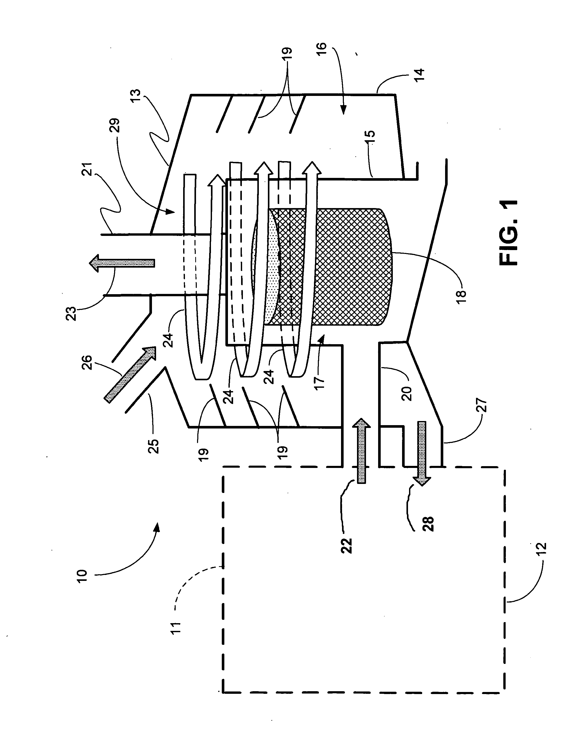
[0013]FIG. 1 shows the preferred embodiment of the apparatus of the present invention, designated generally by the numeral 10. Clothes drying apparatus 10 provides a frame or chassis 11. The chassis 11 contains a known clothes drying chamber 12 that typically rotates when clothes are drying. Frame or chassis 11 can support filtration housing 13. The filtration housing 13 can be mounted directly on the clothes dryer frame or chassis 11, saving space and cost when compared to separate filters and coaxial ducting.

[0014]Filtration housing 13 provides an outer wall 14 surrounding an interior 29 that can include an inner chamber 17 and an outer chamber 16. In FIG. 1, baffle 15 separates filtration housing interior 29 into inner chamber 17 and outer chamber 16.

[0015]Filter or filter screen 18 is contained within inner chamber 17 as shown in FIG. 1. Outer chamber 16 supports one or more annular vanes 19 (e.g. mounted on wall 14) that help create vortex flow within outer chamber 16.

[0016]Hot...


PUM


Abstract

A method and apparatus for removing lint from air that is discharged from a clothes dryer uses a lint filtration housing mounted on the frame of the clothes dryer, the filtration housing having an interior that contains a filter for removing lint from the dryer exhaust air flow stream. The housing provides an influent fitting for transmitting heating exhaust air from the drying chamber to the housing interior. An ambient air supply enables ambient air to be added to the filtration housing interior. One or more vanes is provided that create an annular vortex within the filtration housing interior. The flow of the annular vortex within the filtration housing interior can be between about 500 and 3,000 cubic feet per second. A flow line transmits pre-heated air from the filtration housing interior to the dryer interior.

Description

CROSS-REFERENCE TO RELATED APPLICATIONS[0001]Priority of U.S. Provisional Patent Application Ser. No. 61 / 043,576, filed Apr. 9, 2008, incorporated herein by reference, is hereby claimed.STATEMENT REGARDING FEDERALLY SPONSORED RESEARCH OR DEVELOPMENT[0002]Not applicableREFERENCE TO A “MICROFICHE APPENDIX”[0003]Not applicableBACKGROUND OF THE INVENTION[0004]1. Field of the Invention[0005]The present invention relates to lint collectors for industrial clothes dryers and more particularly to an improved method and apparatus for removing lint from the exhaust air stream of an industrial clothes dryer. Even more particularly, the present invention relates to a method and apparatus for removing lint from the exhaust air stream of an industrial clothes dryer wherein a lint collector is combined with an air heat exchanger that preheats the air supply to the same dryer using the energy from the exhaust stream air. In order to maximize the contact time of the air supply to the exhaust air and ...

Claims


Application Information

Patent Timeline
Patent Type & Authority Applications(United States)
IPC IPC(8): F26B3/02F26B21/00
CPCF26B25/007D06F58/22
Inventor POY, RUSSELL H.
Owner PELLERIN MILNOR
Learn More