Solar photovoltaic support

A technology of solar photovoltaics and photovoltaic panels, applied in the field of solar photovoltaic supports, can solve the problems of inconvenient rotation and adjustment of photovoltaic panels, the inability to maximize the contact time between photovoltaic panels and sunlight, and the low utilization rate of photovoltaic panels to sunlight, so as to improve the utilization rate effect

Pending Publication Date: 2022-08-09
江苏宜柯谷林能源科技有限公司
View PDF0 Cites 0 Cited by
  • Summary
  • Abstract
  • Description
  • Claims
  • Application Information

AI Technical Summary

Problems solved by technology

[0005] The purpose of the present invention is to provide a solar photovoltaic bracket, which solves the problem that the existing solar photovoltaic bracket can only change the angle of the photovoltaic panel facing the sunlight by pushing the fixed plate overturned by the cylinder during use, and it is not convenient

Method used


Image

  • Solar photovoltaic support
  • Solar photovoltaic support
  • Solar photovoltaic support

Examples


no. 1 example

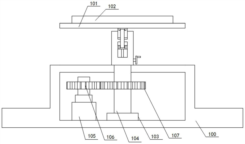
[0026] see figure 1 ,in figure 1 It is a cross-sectional view of the base of the first embodiment of the present invention. The present invention provides a solar photovoltaic support: including a base 100, a mounting plate 101, a photovoltaic panel 102 and a rotating assembly, the rotating assembly includes a bearing 103, a rotating shaft 104, a motor 105, The first gear 106 and the second gear 107 .

[0027] For this specific embodiment, the photovoltaic panel 102 is mounted on the mounting plate 101 . The base 100 is convex, a cavity is provided inside the base 100, and the mounting plate 101 is used to install the photovoltaic panel 102, and the photovoltaic panel 102 is used to convert solar radiation into electrical energy. generate electricity.

[0028] The bearing 103 is fixedly connected to the base 100 and is located inside the base 100, the two ends of the rotating shaft 104 are respectively connected to the bearing 103 and the base 100 for rotation, and the moto...

no. 2 example

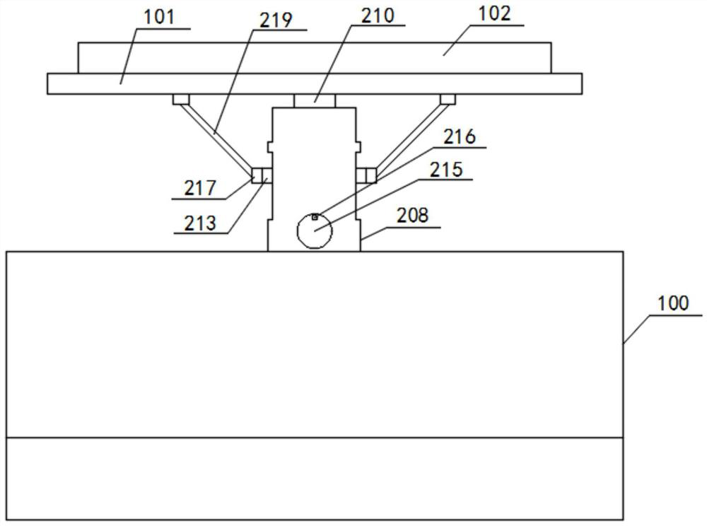
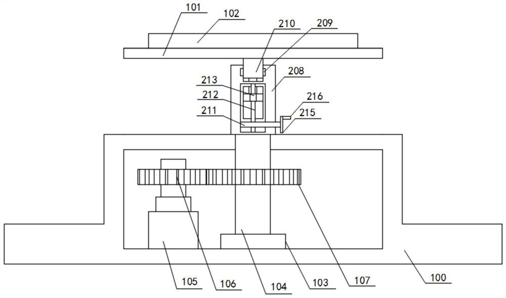
[0031] On the basis of the first embodiment, see Figure 2 to Figure 4 , figure 2 is the overall structural schematic diagram of the solar photovoltaic support according to the second embodiment of the present invention, image 3 It is a sectional view of the base and the installation cylinder of the second embodiment of the present invention, Figure 4 It is a schematic diagram of the connection between the driving block and the slider according to the second embodiment of the present invention. The present invention provides a solar photovoltaic support that further includes an adjustment component, and the adjustment component includes a driving rod 211, a screw 212, a driving block 213, a sliding block 214, The turntable 215 , the handle 216 and the pulling member, the pulling member includes a mounting seat 217 , a connecting shaft 218 and a connecting rod 219 .

[0032] For this specific embodiment, the installation cylinder 208 is fixedly connected to the rotating sh...

no. 3 example

[0039] On the basis of the second embodiment, see Figure 5 and Image 6 , Figure 5 is the overall structural schematic diagram of the solar photovoltaic support according to the third embodiment of the present invention, Image 6 is the invention Figure 5 The enlarged view of A, the present invention provides a solar photovoltaic support that further includes a fixing component, the fixing component includes a mounting block 320 , a support 321 , a fixing rod 322 , an upper fixing block 323 , a spring 324 and a lower fixing block 325 .

[0040] For this specific embodiment, the mounting block 320 is fixedly connected to the photovoltaic panel 102 and is located outside the photovoltaic panel 102 ; the support 321 is fixedly connected to the mounting plate 101 and located on the mounting plate 101 is close to one side of the mounting block 320 ; the fixing rod 322 is rotatably connected with the support 321 . The mounting blocks 320 are installed at the four corners of t...


PUM


Abstract

The invention relates to the technical field of photovoltaic supports, in particular to a solar photovoltaic support which comprises a base, a mounting plate, a photovoltaic panel and a rotating assembly, the rotating assembly comprises a bearing, a rotating shaft, a motor, a first gear and a second gear, the bearing is fixedly connected with the base and located in the base, and the two ends of the rotating shaft are rotationally connected with the bearing and the base respectively. The motor is fixedly connected with the base, the first gear is mounted on an output shaft of the motor, the second gear is mounted on the rotating shaft, the motor is controlled to start, the motor drives the first gear to rotate, the first gear and the second gear are meshed to drive the rotating shaft to rotate, rotation of the rotating shaft is assisted through the bearing, and the rotating shaft rotates to drive the mounting plate to rotate. Therefore, the installation angle of the photovoltaic panel can be rotated and adjusted according to seasons or illumination time periods, so that the contact time of the photovoltaic panel and sunlight is maximized, and the utilization rate of the sunlight by the photovoltaic panel is improved.

Description

technical field [0001] The invention relates to the technical field of photovoltaic brackets, in particular to a solar photovoltaic bracket. Background technique [0002] Photovoltaic, the abbreviation of solar power generation system, is a power generation system that converts solar radiation into electrical energy by using the photovoltaic effect of solar cell semiconductor materials. When laying photovoltaic panels, photovoltaic brackets need to be used, but traditional photovoltaic brackets are only The simple bracket structure can only satisfy the installation work of the photovoltaic panel, and cannot effectively adjust the installation angle of the photovoltaic panel, which reduces the practicability of the use of the bracket. [0003] In an existing solar photovoltaic bracket, the photovoltaic panel is fixed on the surface of the fixed plate, and by activating an air cylinder, the air cylinder pushes the fixed plate to turn over with the right side of the support fra...

Claims


Application Information

Patent Timeline
IPC IPC(8): H02S20/30F24S30/40
CPCH02S20/30F24S30/40Y02E10/50
Inventor 张书乐
Owner 江苏宜柯谷林能源科技有限公司
Why Eureka
Try Eureka