Oxygen concentrator

a concentrator and oxygen technology, applied in the direction of oxygen/ozone/oxide/hydroxide, respirators, separation processes, etc., can solve the problems of wasteful generation of oxygen and excess supply of raw materials, unstable operation of oxygen, etc., to reduce electric power consumption, wasteful generation, and the effect of consuming more electric power

Active Publication Date: 2009-10-15
TEIJIN LTD
View PDF6 Cites 5 Cited by
  • Summary
  • Abstract
  • Description
  • Claims
  • Application Information

AI Technical Summary

Benefits of technology

[0007]While the maximum supply flow rate of the apparatus is the value described above, an actual supply flow rate of oxygen clinically used can be generally set at a low flow rate of 0.25 L / min, 0.5 L / min and the like. In this case, where oxygen is generated at the maximum predetermined flow rate even if a prescribed flow rate is low, oxygen is wastefully generated and consuming more electric power. This leads to an effort to reduce electric power consumption in many apparatuses by an inverter control of a driving motor for a compressor to reduce a volume of raw material air to be supplied from the compressor to an adsorption bed.
[0008]When an attempt is made to secure a volume of raw material air required to supply concentrated oxygen in a high flow rate setting zone in a high flow rate-type apparatus, a volume of raw material air becomes excessive in a low flow rate setting zone to result in excess supply of the raw material. This leads to adsorption of part of oxygen in raw material air on the adsorbents to concentrate unadsorbed argon in the gas generated, as a result, an oxygen concentration in the oxygen concentrated gas generated is reduced.
[0009]A method of reducing a volume of raw material air supplied by lowering the number of revolution of a compressor is applied, but there exist such problems that as a control range in the number of revolution of the compressor is limited, and that its operation becomes unstable when a range in the number of revolution used is too low.
[0010]An object of the present invention is to solve the problems described above and to provide an oxygen concentrator having both functions, of which electric power consumption of the apparatus is reduced and an oxygen concentration in a low flow rate setting zone of an oxygen flow rate supplied from the oxygen concentrator is kept constant.

Problems solved by technology

In this case, where oxygen is generated at the maximum predetermined flow rate even if a prescribed flow rate is low, oxygen is wastefully generated and consuming more electric power.
When an attempt is made to secure a volume of raw material air required to supply concentrated oxygen in a high flow rate setting zone in a high flow rate-type apparatus, a volume of raw material air becomes excessive in a low flow rate setting zone to result in excess supply of the raw material.
A method of reducing a volume of raw material air supplied by lowering the number of revolution of a compressor is applied, but there exist such problems that as a control range in the number of revolution of the compressor is limited, and that its operation becomes unstable when a range in the number of revolution used is too low.

Method used


Image

  • Oxygen concentrator
  • Oxygen concentrator
  • Oxygen concentrator

Examples


Embodiment Construction

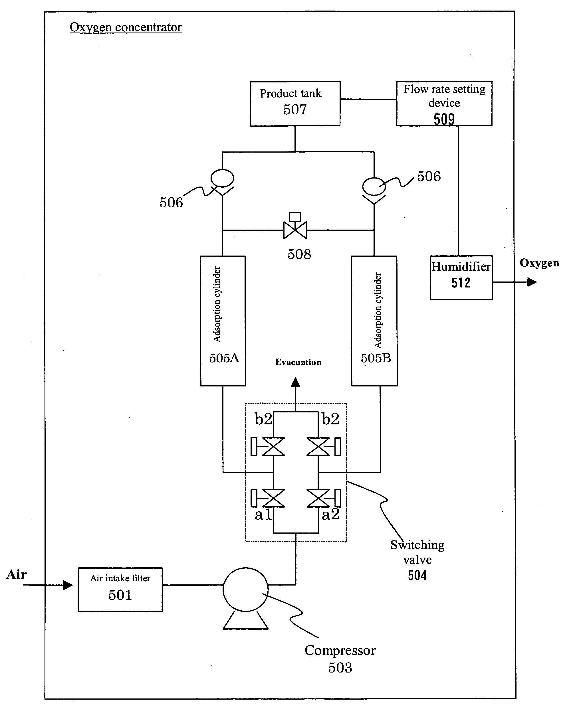
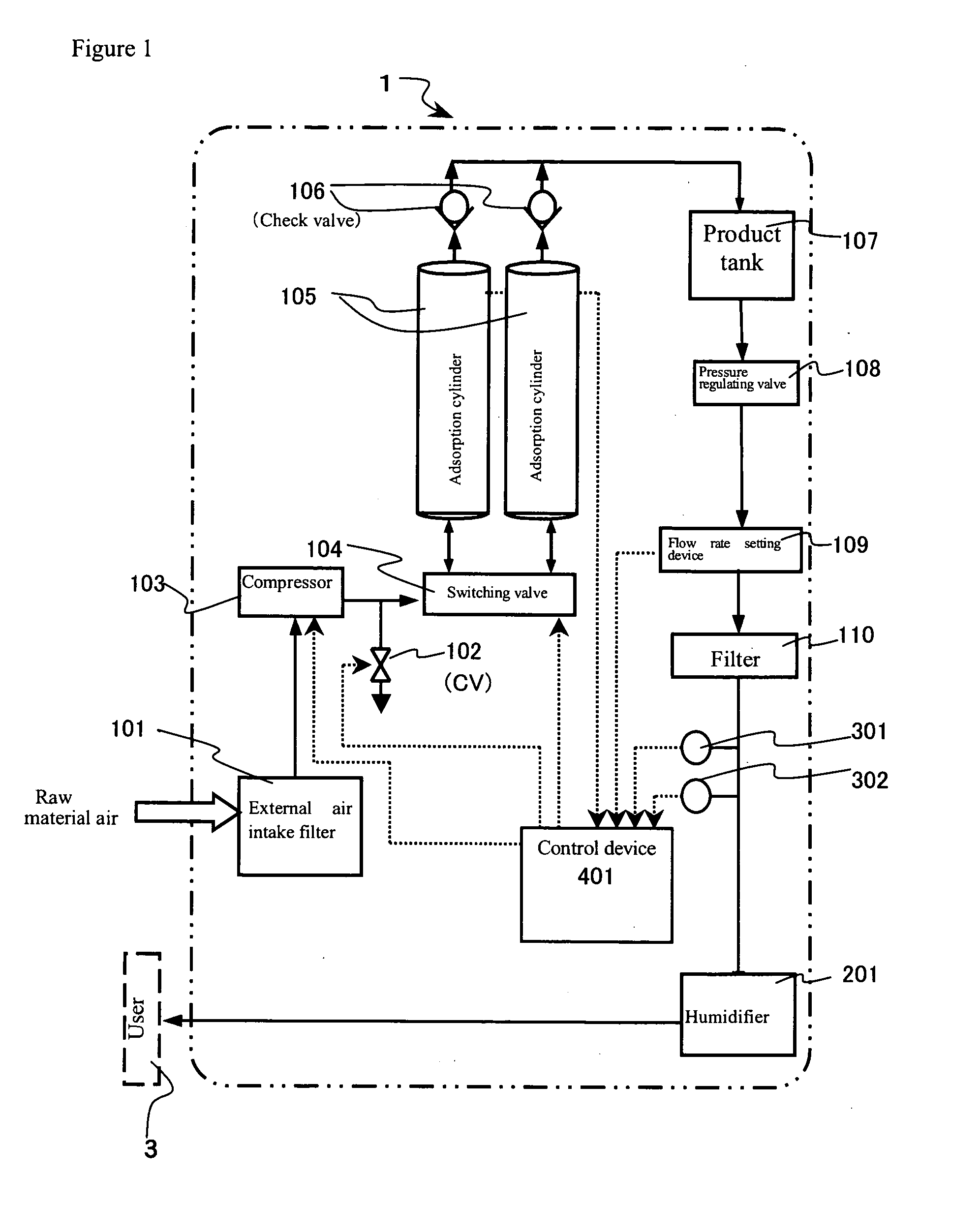
[0040]An example of illustrative embodiment in an oxygen concentrator of the present invention is described using drawings below. FIG. 1 is a schematic constitutional diagram of an apparatus illustrating one embodiment of a pressure swing adsorption-type oxygen concentrator of the present invention. In FIGS. 1, 1 and 3 represent an oxygen concentrator and a user (patient) inhaling humidified oxygen-enriched air, respectively. Pressure swing adsorption-type oxygen concentrator 1 is equipped with external air intake filter 101, compressor 103, switching valve 104, adsorption cylinder 105, check valve 106, product tank 107, pressure regulating valve 108, flow rate setting device 109 and filter 110. With this, oxygen-enriched air can be generated by concentrating an oxygen gas from raw material air brought in from outside.

[0041]Raw material air brought in an oxygen concentrator from atmosphere is first taken in from an air intake port equipped with external air intake filter 101 to elim...


PUM

PropertyMeasurementUnit
flow rateaaaaaaaaaa
flow rateaaaaaaaaaa
flow rateaaaaaaaaaa

Abstract

As an apparatus to prevent the excess adsorption of oxygen molecules caused by excess supply of raw material air and the reduction in the level of generated oxygen caused by concentration of argon, which occur when a predetermined value of an oxygen supply flow rate is in a low flow rate zone, to suppress the electric power consumption and to stably drive a compressor, the present invention provides an oxygen concentrator that is a pressure swing adsorption-type oxygen concentrator equipped with; at least one adsorption bed filled with an adsorbent capable of selectively adsorbing nitrogen relative to oxygen, an air supply device to supply compressed air to the adsorption bed, a flow channel switching device to repeat at a predetermined timing an adsorption step to supply air from the air supply device to the adsorption bed to isolate concentrated oxygen and a desorption step to depressurize the adsorption bed to regenerate the adsorbent therein, and a flow rate setting device to set a volume of concentrated oxygen supplied to a user; comprising an exhaust pipe channel equipped with a leak valve in a flow channel between the air supply device and the adsorption bed to release a part of compressed air that is to be supplied to the adsorption bed into atmosphere.

Description

TECHNICAL FIELD[0001]The present invention relates to an oxygen concentrator to separate oxygen-enriched air or oxygen-concentrated gas from air for use.BACKGROUND ART[0002]In recent years, the number of patients suffering from chronic respiratory diseases such as pulmonary emphysema, pulmonary tuberculosis sequelae, chronic bronchitis and the like has tended to increase because of progress in aging and deterioration in living conditions. Oxygen inhalation therapy to inhale highly concentrated oxygen has been used as an effective treatment method for such patients. Oxygen inhalation therapy is a treatment method for patients with diseases described above to inhale an oxygen gas or oxygen-concentrated gas. A supply source of oxygen gas or oxygen-concentrated gas used in treatment includes a high pressure oxygen cylinder, a liquefied oxygen cylinder, an oxygen concentrator and the like, but the case using the oxygen concentrator has been increased because of durability in continuous u...

Claims


Application Information

Patent Timeline
Patent Type & Authority Applications(United States)
IPC IPC(8): B01D53/047B03C3/36
CPCB01D53/047B01D2253/108B01D2256/12B01D2257/102A61M16/101B01D2259/402B01D2259/4533C01B13/0259C01B2210/0046B01D2259/40007A61M16/107A61M2202/0208A61M2202/03A61M2202/0007A61M16/10B01D53/04C01B13/02
Inventor UCHIYAMA, MITSURUFUJIMOTO, KATSUSHIANDO, MAKOTO
Owner TEIJIN LTD
Why Eureka
Try Eureka