Vibration-proof holder applicable to communication/navigation devices for vehicle use

a technology for communication/navigation devices and vehicle windows, applied in navigation instruments, magnetic bodies, instruments, etc., can solve the problems of affecting the function of navigation devices, affecting the safety of attaching navigation devices b>1/b> to windshield glass through suction cups, and having a simple structure. , the effect of low cost and high applicability

Inactive Publication Date: 2009-10-15
MITAC INT CORP
View PDF2 Cites 14 Cited by
  • Summary
  • Abstract
  • Description
  • Claims
  • Application Information

AI Technical Summary

Benefits of technology

[0010]In summary, the vibration-proof holder applicable to a communications/ navigation device for vehicle use of the present invention is characterized by the provision of a gap-detecting unit for detecting position variations of the communications/navigation device; an electromagnetic control unit configured to adjust the magnetic intensity of the first magnetic body fixedly installed in the communications/navigation device or the second magnetic body disposed in the vehicle body; and a limi

Problems solved by technology

The conventional foot rack 2 as described above is known to have some disadvantages in practical usage.
Specifically, the foot rack is susceptible to vibrations when driving the vehicle over uneven surfaces and on rough/bumpy roads, adversely affecting the function of the nav

Method used


Image

  • Vibration-proof holder applicable to communication/navigation devices for vehicle use
  • Vibration-proof holder applicable to communication/navigation devices for vehicle use
  • Vibration-proof holder applicable to communication/navigation devices for vehicle use

Examples


first embodiment

The First Embodiment

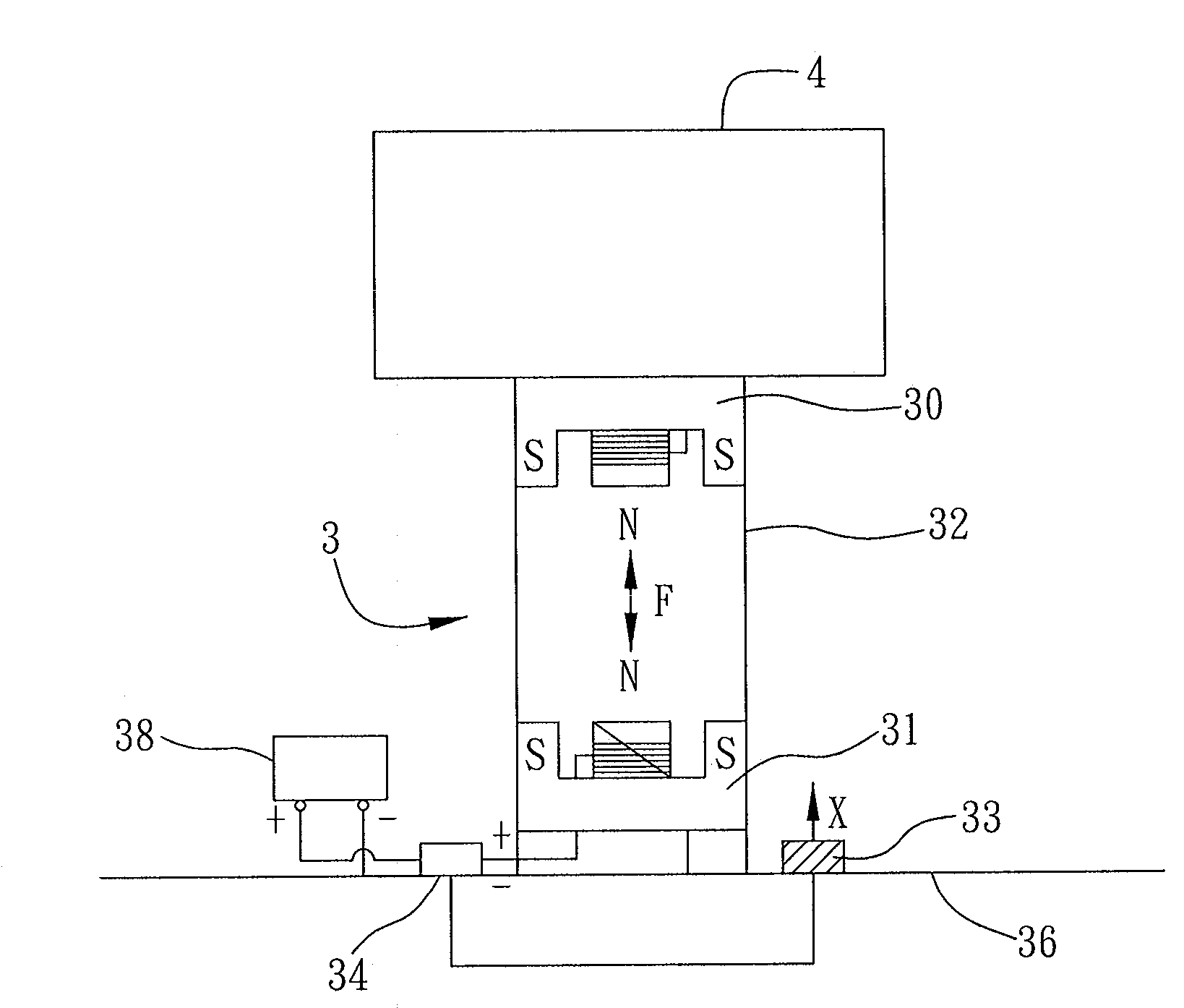
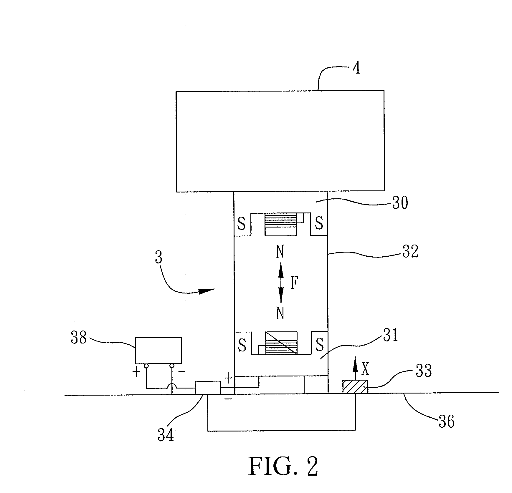
[0017]FIG. 2 depicts a vibration-proof device 3 (hereinafter referred to as vibration-proof holder 3) applicable to a communications and / or navigation device of a vehicle in accordance with a first embodiment of the present invention. In this embodiment, the communications and / or navigation device 4 (hereinafter referred to as communications / navigation device 4) applicable for a vehicle refers to a satellite navigation device for vehicular usage. Note that the communications / navigation device 4 may be other portable electronic device such as mobile phone and Personal Digital Assistant (PDA) and is not limited to that disclosed in this embodiment. The vibration-proof holder 3 is applicable for vehicle use, and more specifically, is to be installed in a vehicle body 36 such as a car body. In other embodiments of the present invention, the vibration-proof holder 3 may be applicable for use with boats, aircraft, etc.

[0018]The vibration-proof holder 3 is comprised of:...

second embodiment

The Second Embodiment

[0029]FIGS. 4A and 4B respectively depict two differing application examples of the vibration-proof holder 3′ applicable to a communications / navigation device used in a vehicle in accordance with the second embodiment of the present invention.

[0030]As described in the first embodiment, the vibration-proof holder 3 is installed to provide the communications / navigation device 4 with vibration-proof effect in a vertical direction. The second embodiment differs from the first embodiment only in that the second embodiment provides the communications / navigation device 4′ with vibration-proof effect in a horizontal direction.

[0031]As illustrated in FIG. 4A, the communications / navigation device 4′ is connected to the vibration-proof holder 3′ by coupling or affixing to an end of a connecting rod 37′, or by means of a fixed base, and another end of the connecting rod 37′ is fixedly connected to the first magnetic body 30′. The first magnetic body 30′ connects with the li...


PUM


Abstract

A vibration-proof holder applicable to a communications/navigation device for vehicle use is provided, characterized by the use of a gap-detecting unit to detect position variations of the communications/navigation device, and an electromagnetic control unit to adjust magnetic intensity of magnetic bodies fixedly installed in the vehicle, wherein first and second magnetic bodies are limited to remain in the same track and to face one another with the same magnetic polar end thereof, such that the communications/navigation device can return to its initial position to achieve the vibration-proof effect.

Description

BACKGROUND OF THE INVENTION[0001]1. Field of the Invention[0002]The present invention generally relates to a vibration-proof holders applicable to electronic communications and / or navigation devices, and more particularly, to a vibration-proof holder applicable to electronics devices for use in vehicles.[0003]2. Description of the Related Art[0004]The integration of satellite navigation (GPS) devices with communications devices such as cell phones is increasingly popular, especially for portable navigation products. Navigation devices are widely used in automobile vehicles nowadays and such navigation devices are typically held in place by a conventional fastening mechanism such as that depicted in FIG. 1. As illustrated, the navigation device 1 for use in vehicles is held by a support mount that includes a complementary foot rack 2 configured to hold the navigation device 1 in place by coupling the navigation device 1 to a fixed base 20 on an end of the foot rack 2. The fixed base ...

Claims


Application Information

Patent Timeline
IPC IPC(8): H01F7/20
CPCB60R11/02B60R11/0241B60R11/0258B60R2011/0057H01F7/1646F16F15/03G01C21/265G01C21/36H01F7/066F16F6/00
Inventor CHENG, YU-CHI
Owner MITAC INT CORP
Why Eureka
Try Eureka