Reducing power dissipation in portable LCOS/LCD/DLP portable projection systems

a projector system and power dissipation technology, applied in the field of projector systems, can solve problems such as affecting white balance behavior, color fidelity and image quality, degrading image quality, and adjustment of white balance and contrast, and achieve the effect of reducing power consumption

Active Publication Date: 2009-10-15
MACOM TECH SOLUTIONS HLDG INC
View PDF23 Cites 43 Cited by
  • Summary
  • Abstract
  • Description
  • Claims
  • Application Information

AI Technical Summary

Benefits of technology

[0010]To overcome the drawbacks of the prior art and to provide additional benefit a projection system and method of operation is disclosed which reduces power consumption. In one embodiment and as disclosed herein, a method is provided for generating a projected image where the image comprises multiple image pixels and for each color the method comprises receiving and processing image data to create pixel matrix control data and light source control data. Also part of this method is the step of providing the light source control data to one or more light sources to selectively control output intensity of the light source on a frame by frame basis. Then providing the pixel matrix control data to one or more pixel matrixes to selectively control the opaqueness of the pixels of the one or more pixel matrixes on a frame by frame basis. As part of this method, for a particular frame, the output intensity of one of the one or more light sources is set at a level by means of amplitude, pulse width modulation, or both. This in turn will yield a desired color intensity for the image pixel with the highest color intensity and a corresponding pixel in the pixel matrix is set to not reduce the light intensity passing there-through.
[0014]Also disclosed is a projection system comprising one or more light sources configured to generate light output at an intensity determined by one or more light source control signals and one or more pixel screens having one or more pixel areas controllable to varying levels of translucency based on one or more pixel screen control signals. Also part of this system is a controller configured with one or more inputs configured to receive image data and a processor configured to process the image data to create the one or more light source control signals and the one or more pixel screen control signals. One or more outputs are configured output the one or more light source control signals to the one or more light sources and the one or more pixel screen control signals to the one or more pixel screens. Thus, on a frame by frame basis, the light output has an intensity or duration matching a maximum light intensity for a particular frame to thereby reduce power consumption.
[0016]In yet another embodiment, a projection system controller for controlling projection of an image is disclosed. In this system a controller has an input configured to receive image data and a light source control signal output configured to output one or more might source control signals. A pixel matrix control signal output is configured to output one or more pixel matrix control signals and a processor is configured and provided to process the image data to generate and synchronize the one or more pixel matrix control signals with the one or more light source control signals to reduce power consumption of one or more light sources. This occurs by matching a light intensity output, light output duration or both from the one or more light sources to a light intensity for any one of the one or more brightest pixels in the image.

Problems solved by technology

A drawback of prior art projection systems is that over time or at different temperatures, the projection system may evidence inconsistent intensity of the various light sources due to different rate of aging of the light sources or different temperature of the same which will impact white balance behavior, color fidelity and image quality.
The drawback of this approach is that the white balance and contrast are adjusted for a particular temperature when the system is assembled in the factory.
However, as the temperature changes, given the probable different behavior of the light sources across temperature, the white balance and contrast deviates from the optimal value which in turn degrades image quality.
Also light source aging will occur and might be different for the 3 different light sources and this will have similar unwanted impact on image quality.
In these systems generally a set of fans, heatsinks and / or TE coolers are employed to try to maintain operating temperature constant and minimize these effects, however start-up (cold) condition might require a warm-up time and TE-coolers and fans consume additional power.
These two aspects and the lessening picture quality does not make this solution appealing.
The main drawback of this approach is the fact that light sources characteristic change significantly from vendor to vendor and even from light source to light source provided by the same vendor especially when light sources come from different batches.
This puts a huge burden on the production because a look-up table needs to be built for every light source and for different temperatures.
This is extremely time consuming and expensive (both from a cost of equipment and production test time standpoint).

Method used


Image

  • Reducing power dissipation in portable LCOS/LCD/DLP portable projection systems
  • Reducing power dissipation in portable LCOS/LCD/DLP portable projection systems
  • Reducing power dissipation in portable LCOS/LCD/DLP portable projection systems

Examples


Embodiment Construction

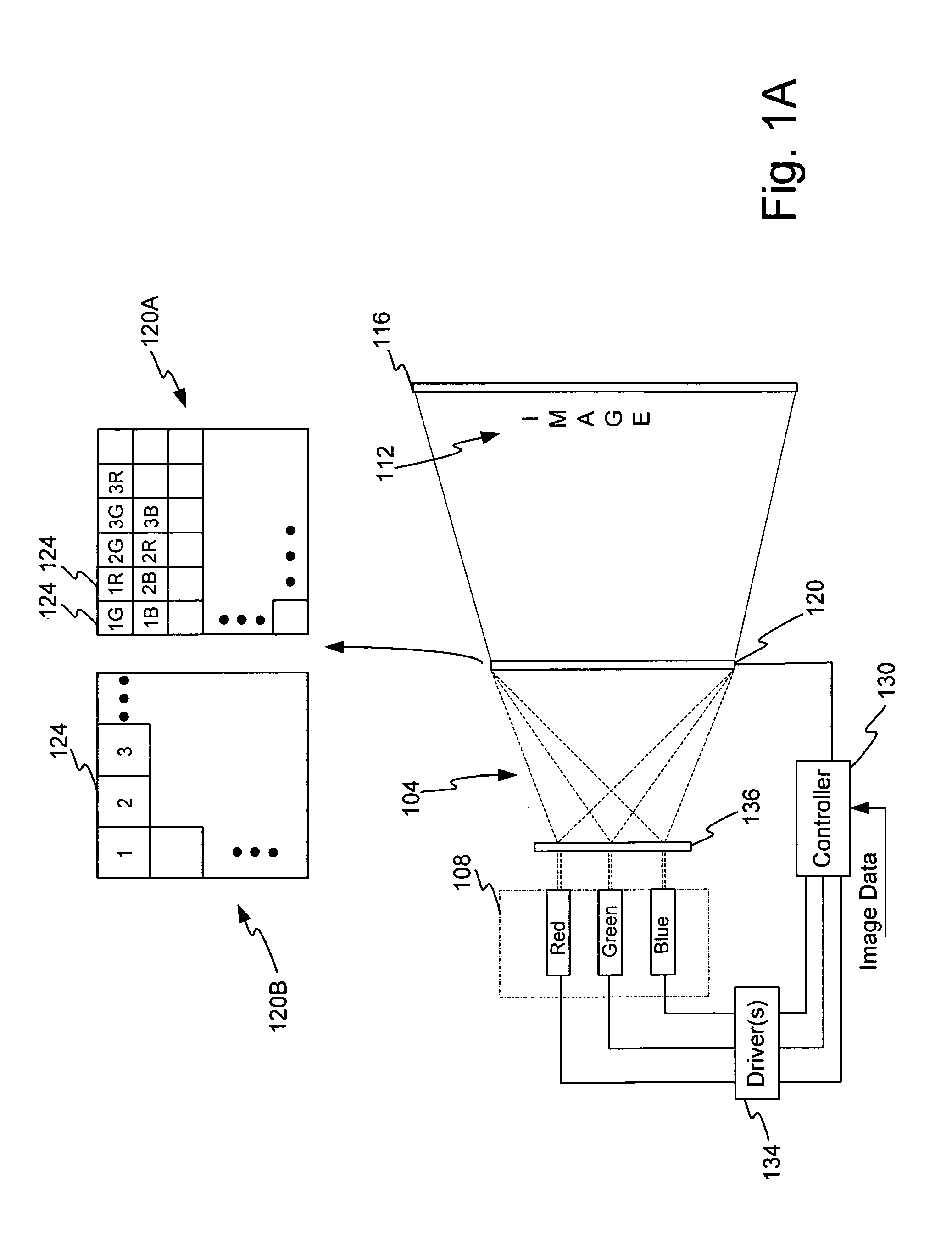
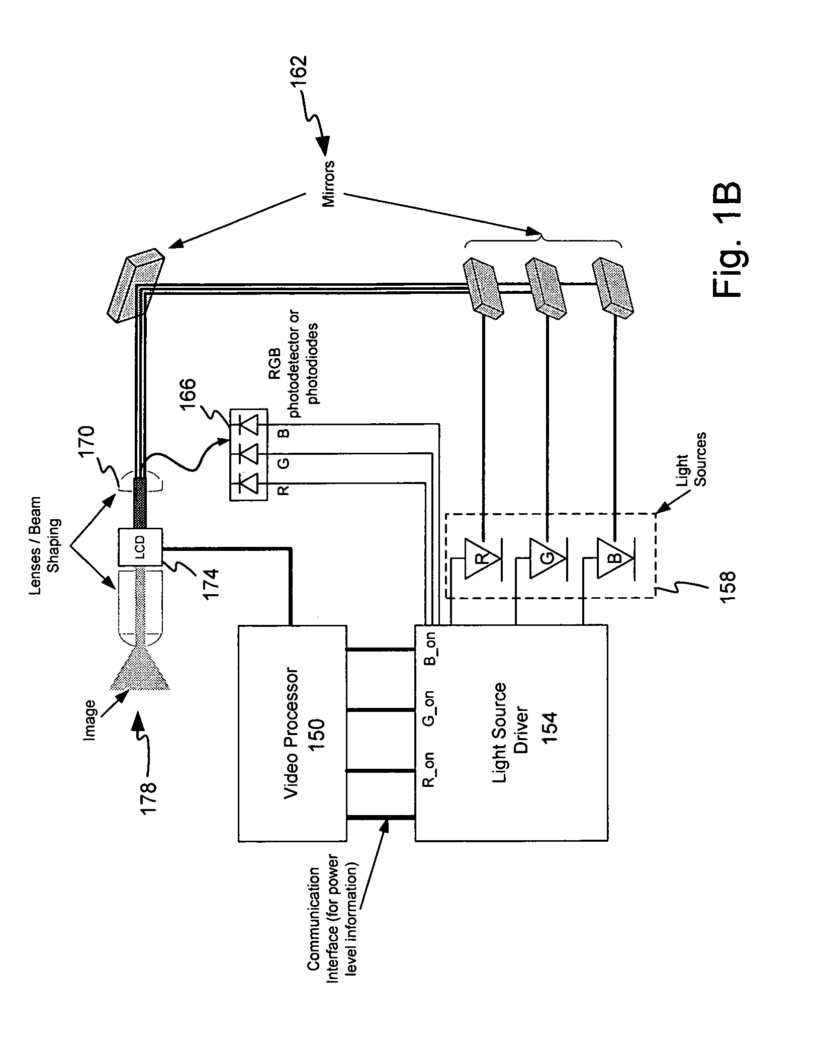
[0030]In an example environment shown in FIGS. 1A and 1B, a projector system is disclosed wherein light 104 is provided by 3 light sources 108, such as a red light source, green light source and blue light source. In other embodiments, different number of light sources may be utilized. The light sources 108 may comprise a laser, LED, or any other light source. The output of the light sources is provided to an optical system 136. In this embodiment, the optical system 136 comprises one or more lenses, mirrors, or both. The optical system 136 directs or focuses the light to a pixel matrix 120. The optical system 136 may be passive or active. The image 112 is created by shining on and filtering these colors through the pixel matrix 120. In one embodiment, the pixel matrix 120 is an LCD / LCoS system. In other embodiments it can be a DLP engine. The pixel matrix 120 is a matrix of pixels 124 where each one can be made transparent or opaque to light, or some level of opaqueness between tra...


PUM


Abstract

A projection system with one or more light sources reduced power consumption and optional scanning capability is disclosed. A controller processes image data to generate light source control signals and pixel screen control signals which are coordinated to generate an image. Reductions in power consumption occur by matching the light output from the light source to the brightest pixel(s) in the pixel screen for a particular frame. By setting the light output level to an intensity or duration matched to only the maximum level corresponding to a image frame, power consumption is reduced as compared to an embodiment which sets the light source output to its maximum level or maximum duration. The pixel screen, which may be an LCD screen, sets pixel areas corresponding to the brightest pixels as transparent and other, less bring pixels on the pixel screen are set to appropriate levels of reduced transparency.

Description

PRIORITY CLAIMS[0001]The application claims priority to and the benefit of U.S. Provisional Patent Application 61 / 072,446 filed Mar. 31, 2008 entitled Reducing Power Dissipation in Portable Projection Systems and U.S. Provisional Patent Application 61 / 190,978 filed Sep. 3, 2008 entitled Reducing Power Dissipation in Portable Projection Systems with Scanning Apparatus.FIELD OF THE INVENTION[0002]The invention relates to projector systems and in particular to a method and apparatus for reducing power consumption of projector systems.RELATED ART[0003]Projection based display systems are a popular and widely used method to project an image upon a large screen for viewing by one or more people. Projection systems have numerous advantages over enclosed systems including larger image size in relation to the size of the projection system, portability, and cost. However, current projection systems are capable of improvement. One such improvement may be in the form of reduced power consumptio...

Claims


Application Information

Patent Timeline
Patent Type & Authority Applications(United States)
IPC IPC(8): H04N9/31G09G5/10G09G3/36
CPCG09G3/2011G09G3/2018G09G3/3426G09G3/3611H04N9/3197G09G2330/021H04N9/3155H04N9/3161H04N9/3179G09G2320/0646
Inventor BAZZANI, CRISTIANODRAPER, DANIEL
Owner MACOM TECH SOLUTIONS HLDG INC
Why Eureka
Try Eureka